Area Profile Generation
This section of the documentation highlights the basic concept behind area profile generation, which is essential in the analysis of axial piston machines. When Modeling APMs, the orifice equation is used to approximate the flow into and out of the displacement chambers. However, this equation relies on an estimate of the minimum opening areas between displacement chamber and the inlet or outlet ports. Area profile can be generated with the help of analytical calculation and also by using CFD solver AVAS (AVAS documentation). In this tutorial our main focus will be on the analytical approach and it will be demonstrated with the help of an example.
Basic Idea
Area profile basically represents the minimum overlapping area between the displacement chamber port and the valve-plate opening. There are two main flow area to be considered such as groove and the kidney port opening. Our first step would be calculating cross sectional area when displacement chamber port overlaps with the valve-plate opening at certain situations.
When the displacement chamber port overlaps the groove of the valve plate, we can assume a triangular cross sectional area perpendicular to the slope the groove, and when it overlaps the kidney port opening, we can consider the surface area of the displacement chamber port for simplicity.
However, it is worth noting that the displacement chamber port may not always be the same size as the kidney opening. If the displacement chamber port doesn’t overlap with any of the opening area, the cross sectional area should be considered zero. In the rest of the overlapping scenarios we can populate the area curve using suitable interpolation method.
Above mentioned methodology is demonstrated below with the help of a reference valve plate.
Reference Valve Plate
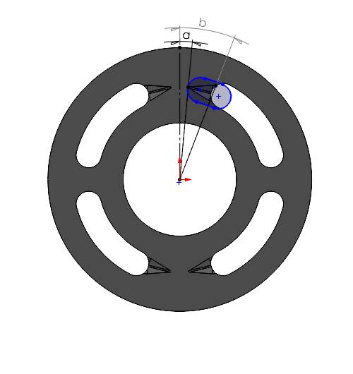
A valve-plate is presented in figure 1. It has two kidney opening in each of the high and low pressure side. All the kidney opening has one groove.
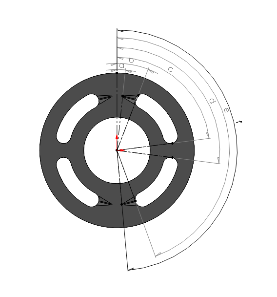
We have to measure the angles representing each groove opening and ending as well as the starting and ending of each kidney port as shown in the figure. Those angles are useful to calculate the center of the displacement chamber port at the considered location which is required to plot the area profile.
The following table demonstrates the angles of certain positions on the right side of the valve-plate with respect to the vertical axis:
Angle |
Description |
|---|---|
a |
Starting point of the upper groove. |
b |
End point of the upper groove. |
c |
End point of the upper kidney opening on the valve-plate. |
d |
Starting point of the lower kidney opening on the valve-plate. |
e |
End point of the lower groove. |
f |
Starting point of the lower groove. |
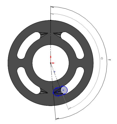
Required Overlapping scenarios
We should consider the following cases to plot the area profile:
1. When the displacement chamber port touches the starting of the groove
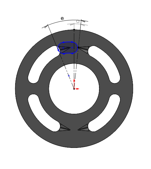
At this point, the displacement chamber port doesn’t overlap with the +x side of the kidney opening, as a result the considered area should be zero. The angle made by the center of the displacement chamber port is equal to the \((\angle a - \frac{\theta}{2})\). Here, \(\theta\) represents the angle span covered by the displacement chamber port.
If the port covers the other side of the groove, we shouldn’t consider that area at this point for the considered pressure side. That overlapping area should be considered while calculating for the other side.
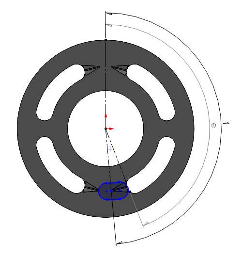
2. When the displacement chamber port starting point touches the end of the groove
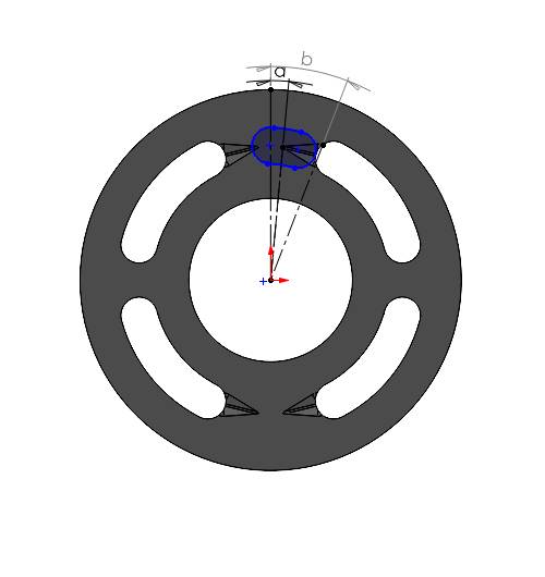
Here, the displacement chamber port completely covers the groove and we need to consider the area of the triangular cross section at the end of the groove. Width and height of the groove at the end can be measured from the CAD file. Angle made by the center of the port will be equal to \((\angle b - \frac{\theta}{2})\).
3. When the port end touches the starting of the groove
Here, the port covers the whole groove as well as the kidney opening partially. We have to consider the triangular cross sectional area (calculated in the previous step) and the partial overlapping area, which can be linearly interpolated with the angle span covered by displacement chamber port. For example, the displacement chamber port has an angle span of 20 degree and surface area of 100 mm2. But it covers only 10 degree angle span of the kidney port opening, we can assume that the approximate overlapping area would be \(\left(\frac{100}{20}\right) \times 10 = 50 \text{ mm}^2\).
Finally we need to add those two area to get the contributing area. The angle made by the center of the displacement chamber port is equal to the \((\angle a + \frac{\theta}{2})\).
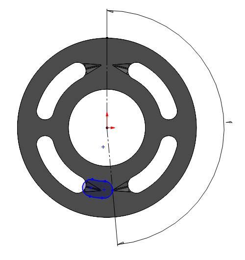
4. When the port completely enters the kidney opening and up to when it stays inside

In both of the above cases, the displacement chamber port completely overlaps the kidney port opening, as a result the surface area of the port should be considered as the overlapping area. It can be measured from the CAD file. Here we have 175 mm2. we will have the same overlapping area as long as the port is completely inside the kidney opening. The angle made by the center of the displacement chamber port will be equal to the \((\angle b + \frac{\theta}{2})\) and \((\angle e - \frac{\theta}{2})\) respectively. In the considered valve-plate, there is a gap between two kidney openings (between angle d and angle c) or no overlapping zone. However, we are considering a continuous opening to keep the example simple as the purpose of this documentation is to provide a basic idea. Between c and d, you might consider interpolating the overlapping area for more accuracy.
5. When the displacement chamber port starting point touches the starting point of the groove
It is same scenario as mentioned in case 3. However, the dimensions of the groove and the overlapping span might be different depending on your case. You need to calculate area and angle of the port center accordingly. Here, we have same dimensions for simplicity.
6. When the displacement chamber port end point touches the end point of the groove
In this case we need to consider the triangular cross section area perpendicular to the slope of the groove. Again, the width and height of the cross section can be measured from the CAD.
The angle made by the center of the displacement chamber port is equal to the \((\angle e + \frac{\theta}{2})\).
7. When the displacement chamber port completely exits the groove
A the port leaves the groove completely, the overlapping area is zero for the considered side. The angle made by the center of the displacement chamber port is equal to the \((\angle f + \frac{\theta}{2})\).
Here, we have discussed about the required points in one pressure side. Similarly, we have to proceed for the other pressure side. If we have symmetry in both side, we can use the calculated area, shifting the center of the port by 180 degree.
Plotting
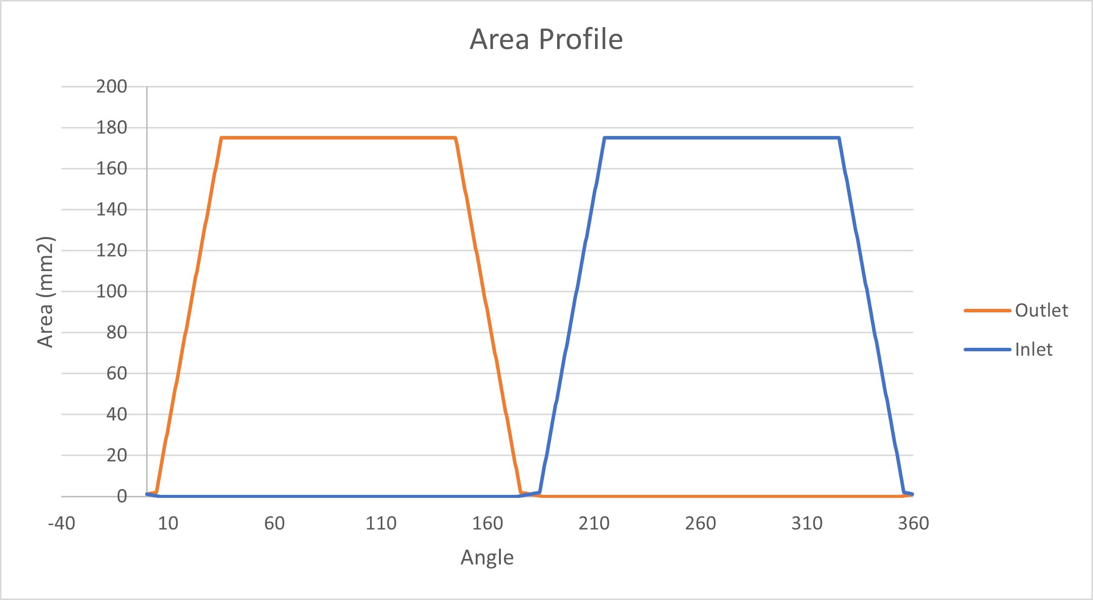
Once we have all the required area and corresponding center angle, we can generate the area profile. When transitioning over the groove, we can populate the area profile using linear interpolation. Feel free to use MATLAB or any other utilities for interpolation. As long as the port is inside the kidney opening completely, we can consider same overlapping area for the measured angle span. Once, the port leaves the last groove of the considered side, the overlapping area should be zero for the rest of the span.
Remember, area profile consists of overlapping area between both high and low pressure side. Therefore, do not forget to calculate for the other side. In the end the area profile should have two curve as below: