Gerotor
This tutorial is for modeling gerotors.
What is a Gerotor Pump?
A Gerotor pump is a type of gear pump that moves fluid from a low-pressure region to a high-pressure region. The word is derived from Generated Rotor as the outer rotor is generated from an inner rotor or vice-versa.
A Gerotor pump displaces fluid by trapping the fluid in its Tooth Space Volume (TSV) and supplies the fluid from the suction to the delivery port.
How to Simulate a Gerotor
The basic sketch of how to simulate a complete gerotor model is shown below.
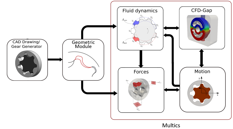
First, we need to define the requirements for simulating a Gerotor and they are the following:
Geometry Generation
Gear profiles
Port profiles
Geometry Input
Geometry Output file conversion
Sketch Creation
inputDict Definition
Geometry Generation
Gear profiles
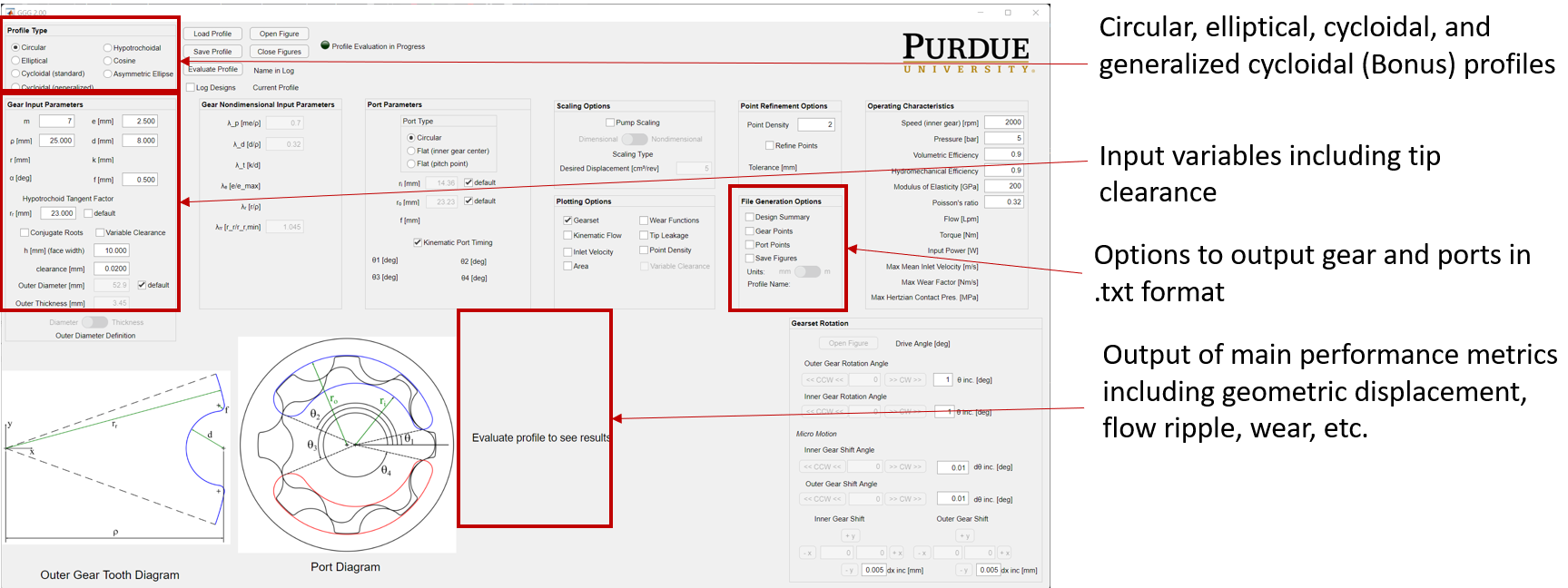
To generate geometry, we need gear profiles of both inner and outer, inlet and outlet port STL/TXT file, and the geometry input files. These files can be generated by the tool GerotorGeometryGenerator2.0.exe which is located in Multics/Utilities/Gerotor/. A snapshot of the tool is provided below.
Attention
Make sure to run the application as an Administrator.
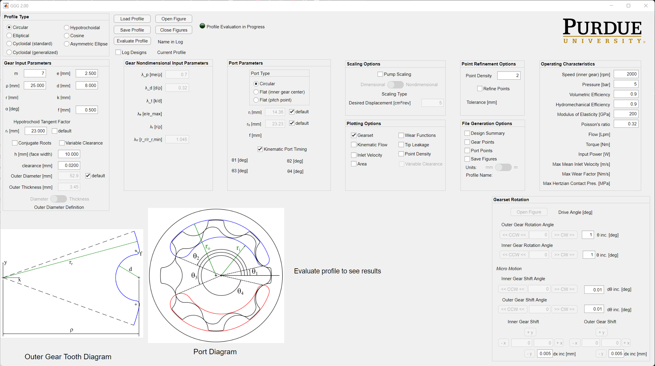
Please explore the tool and some of tips stuff that the tool can do is in the images below.
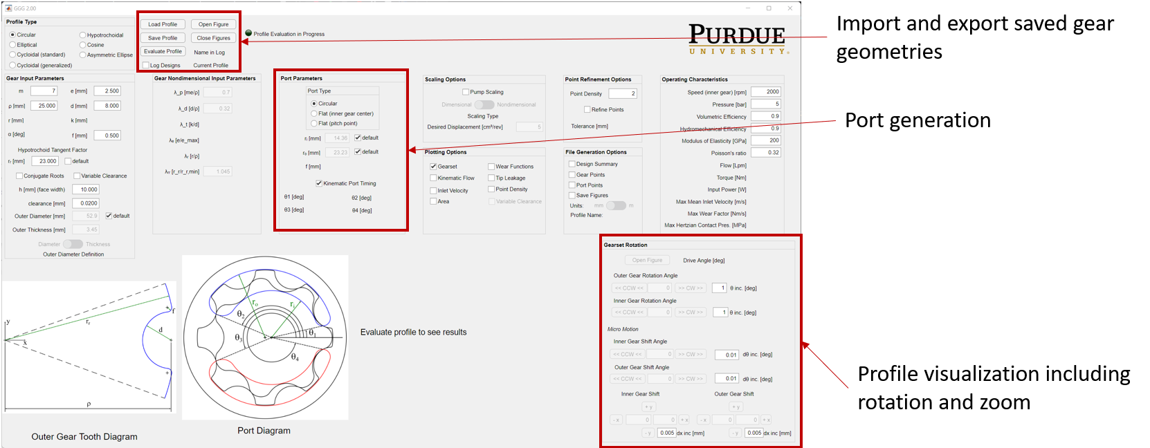
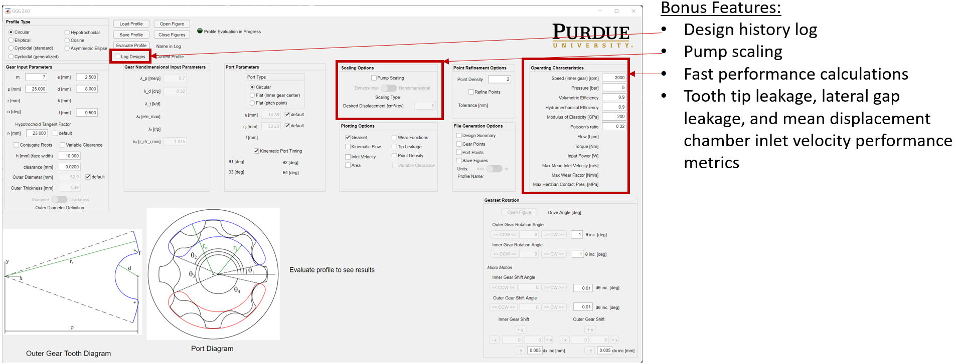
Finally, to generate the outputs for the Geometry Preprocessor Code to run make sure the options mentioned below are checked and then click on Evaluate Profile.
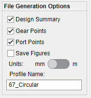
Once these options are selected the final folder should contain the files mentioned below.
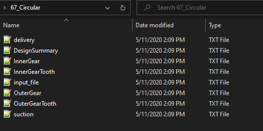
This concludes generation of the files and the use of geometry generation.
Preprocessor
The preprocessor code is called GerotorFSI_2.0.exe which is located in Multics/Utilities/Gerotor. Please install this software.
Once the installation is complete. The startup screen for the software looks like this.
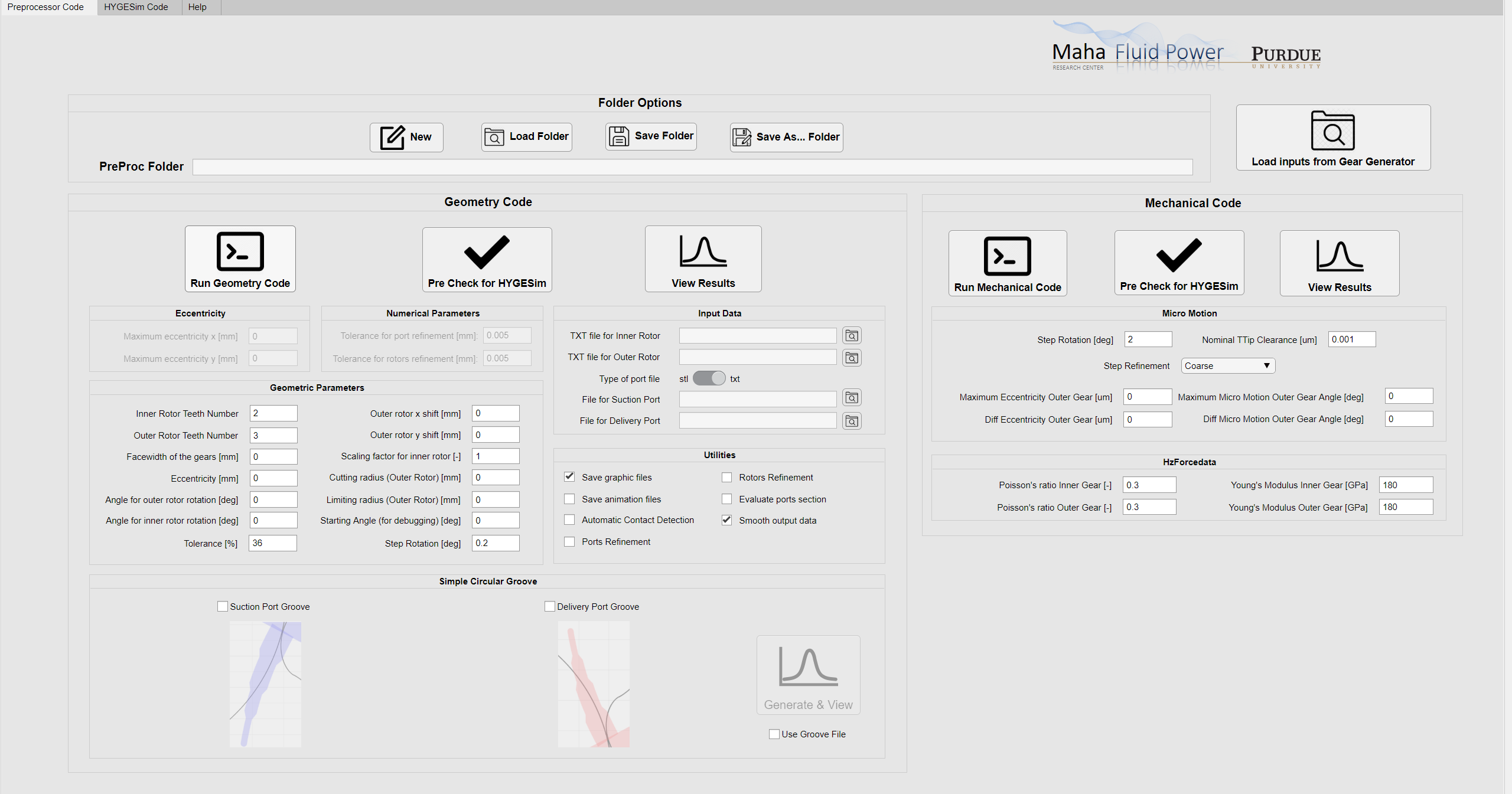
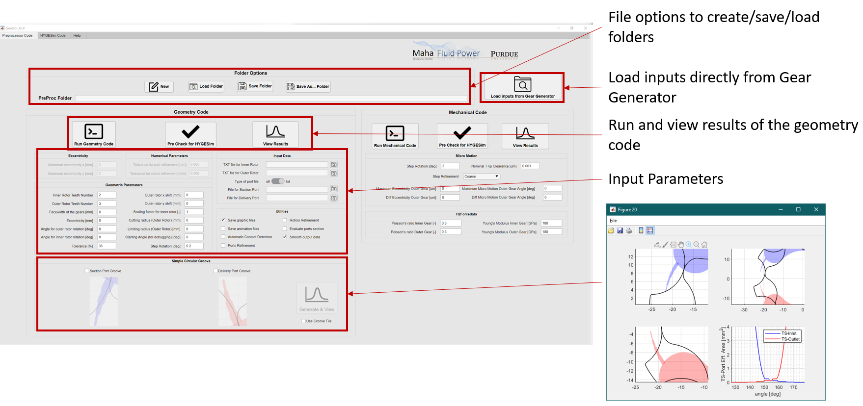
The features of the preprocessor are mentioned in the images below.
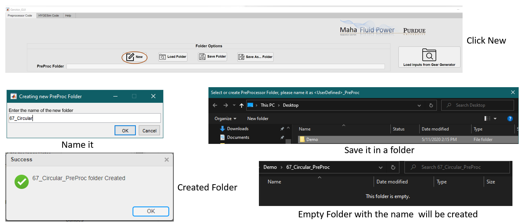
Next, to generate necessary outputs for the preprocessor follow perform the following steps:
Create New PreProc Folder.
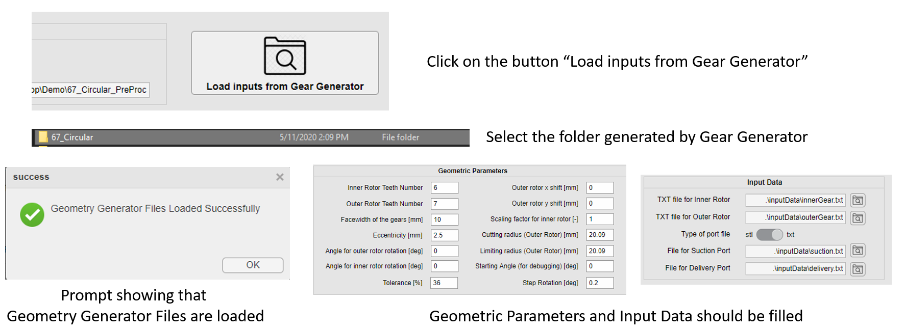
Load inputs from Gear Generator.
Port profiles
The port profiles can be either in the form of STL or TXT format where the TXT files are in similar format as to the ones from gear profiles. Also, to generate STL files make sure that you perform the following procedure.
Import the port file in SolidWorks or any other software of your choosing.
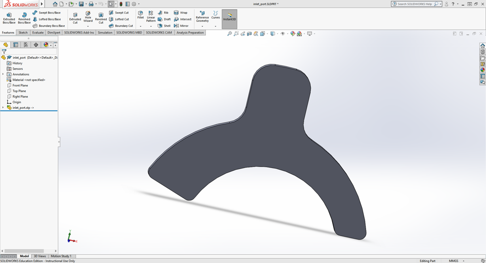
Export it as STL and click on the following options:
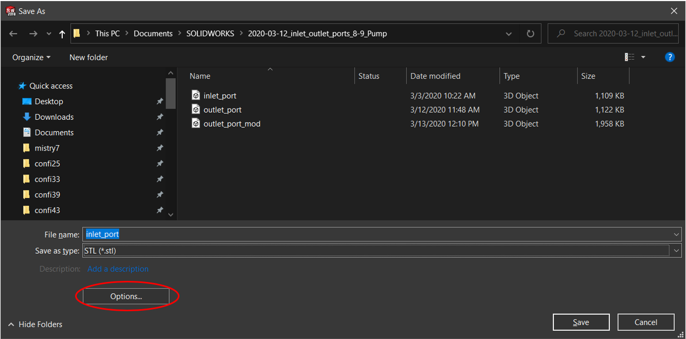
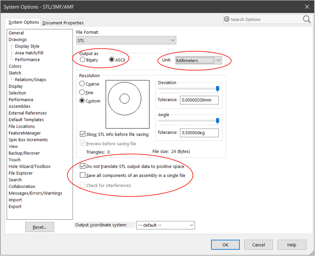
Some of the STL options that are to be kept in mind while exporting are :
Output should be ASCII
Unit Millimeters
Check “Do not translate STL output data to positive space”
Save port Profiles.
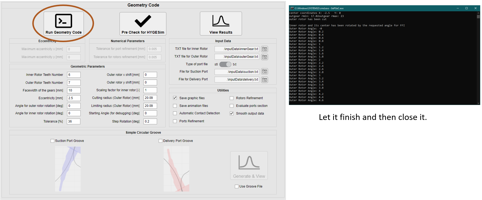
Run Geometry Code.
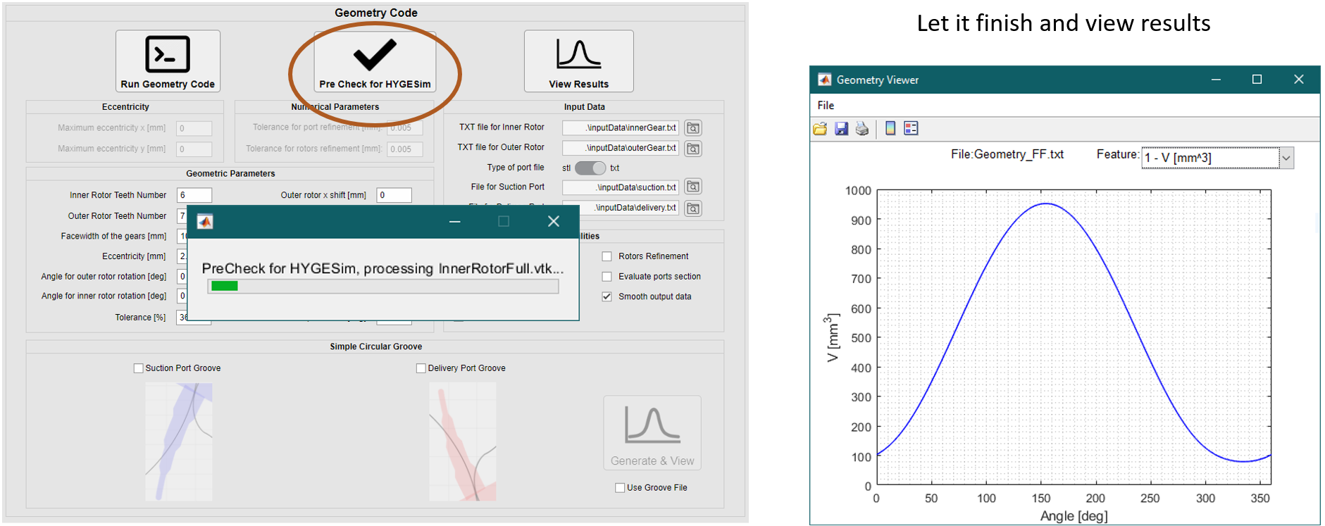
Check Geometry Code Outputs.
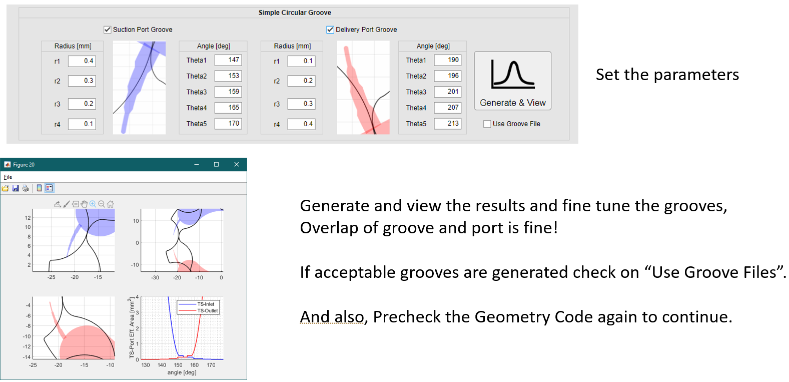
Using Groove in Geometry Code.
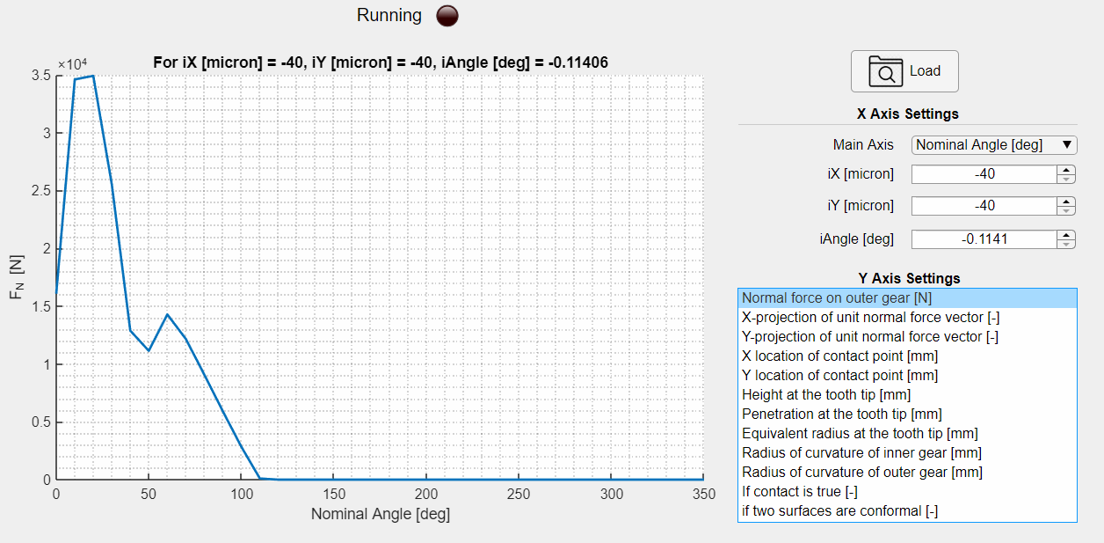
Run Mechanical Code.
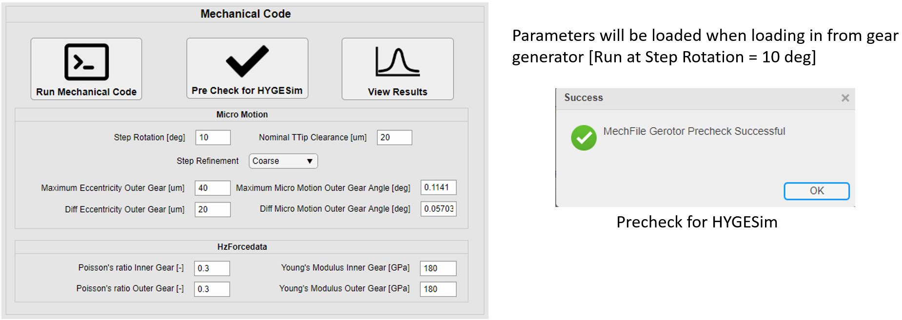
View Results Mechanical Code.
Finalization of Geometry Code.
Both initial checks must be done successfully for the simulation to proceed further. If you plan to close the window, please click save folder, then you can continue the work.
Geometry Inputs
The next step is to run the geometry code. For the exe please reach out to the Multics team for the necessary input files. The geometry run folder should consist of these folders and TXT files as shown in the picture below.
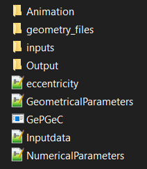
A brief description of each folder:
AnimationFolder : Stores all the TXT files in point of various geometries during the run of geometry code.geometry_filesFolder : Stores all the necessary files including an important file “Geometry_FF.txt” which is used in Multics.inputsFolder : Stores files for inner gear, outer gear, inlet and outlet ports.OutputFolder : Stores vtk files to view in Paraview.eccentricity.txt: can be used to assign a specific shift in eccentricity before running the simulation.Maximum eccentricity x [mm]: 0.0 Maximum eccentricity y [mm]: 0.0
GeometricalParameters.txt: Other inputs necessary for geometry code run. Some default values are given below.Inner Rotor Teeth Number 7 Outer Rotor Teeth Number 8 Facewidth of the gears [mm] 16.0 Eccentricity [mm] 1.7 Angle for outer rotor rotation [deg] 0.0 Angle for inner rotor rotation [deg] 0.0 Tolerance [%] 36.0 Outer rotor x shift [mm] 0.0 Outer rotor y shift [mm] 0.0 Scaling factor for inner rotor 1.0 Cutting radius (Outer Rotor) 18.0 Starting Angle (for debugging) 0.0 Step Rotation (deg) 0.5
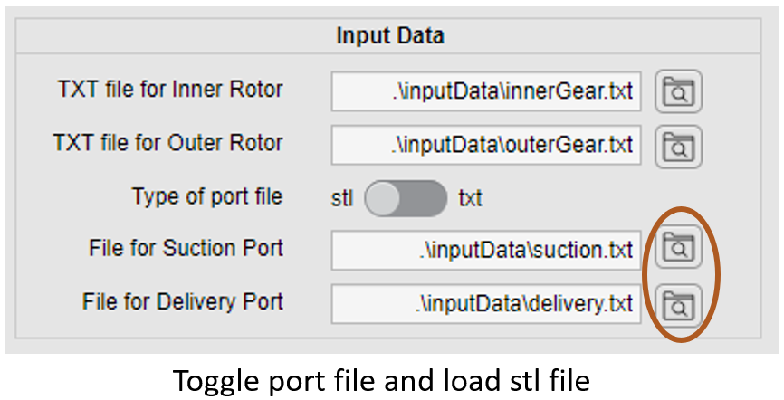
Inputdata.txt: contains locations for the TXT and STL files.TXT file for Inner Rotor: ./inputs/InnerRotor.txt TXT file for Outer Rotor: ./inputs/OuterRotor.txt Type of port file [STL/TXT] STL TXT file for Suction Port: ./inputs/InletPort.STL TXT file for Delivery Port: ./inputs/OutletPort.STL
NumericalParameters.txt: Contains information to refine rotors and ports.Tolerance for port refinement [mm]: 0.01 Tolerance for rotors refinement [mm]: 0.005
These files along with the exe file :
GePGeC.execonstitute the geometry folder.
Geometry Output file conversion
There are a few MATLAB scripts that perform the Geometry Output file conversion. The first one is GeometryFFtoHygesim.m which converts Geometry_FF.txt to the file that can be read by Multics. Other important scripts are GenerateJournalSnap.m and GenerateSnapPolygon.m. These files are important to create polygon series which are used for the lateral gap model.
Sketch Creation
This part is to give the users a brief understanding as to how the existing gerotor sketch is made. There are some Gerotor specific functions that needs to be understood. One of them is GearPositionGerotor that needs to be used in the fashion shown below.
GearPositionGerotor Position(dictInOut, // input/output dictionary (for adding printable features)
    z, //Number of teeth
    ecc, // Nominal Eccentricity of Gerotor
    isMicroMotion,
    USE_MECH_PREPROC_FILE
);
Sys.storeNode(Position);
Other than this, we would also require import of Geometry file and Fluid File. This can be done using GeometryTable and FluidTable functions respectively. Both the gear bodies are initialized with the function ExternalGear as shown below.
ExternalGear driveGear(
    dictInOut, //!< input/output dictionary (for adding printable features)
    "Gear_1",//!< Name of features for adding dictionary features
    "Drive Gear", //!< Brief description of feature for output list
    Position, //!< Gear position object
    GearPositionGerotor::DriveGearID,//!< Gear ID, used when getting ex/ey and appending force/moment so gearpos knows which gear to assign to

    EDrive, //!< Young's Modulus
    faceWidth, //!< Depth of gear
    faceWidth + 2. * driveLenJb * shaftSupportPos, //!< length to support

    faceWidth / 2. + driveLenJb / 2., //!< Z coordinate of center of top bearing
    -faceWidth / 2. - driveLenJb / 2., //!< Z coordinate of center of bottom bearing

    driveDiameterJb / 2., //!< Radius of shaft
    sqrt(pow(driveDiameterJb / 2.,2) + pow(rMaxDrive,2)), //!< Effective gear radius (equivalent cylinder) for area moment of inert.

    rMaxDrive, //!< Radius at top of gear (-z direction)
    rMaxDrive, //!< Radius at bottom of gear (+z direction)
    0., //!< X Eccentricity from shaft center of top cross-section gear center
    0., //!< y Eccentricity from shaft center of top cross-section gear center
    0., //!< X Eccentricity from shaft center of bottom cross-section gear center
    0., //!< y Eccentricity from shaft center of bottom cross-section gear center

    isMicroMotion, //!< Flag corresponding to if the body is capable of moving XY
    0, //!< Flag corresponding to if the body is capable of moving Z
    0, //!< Flag corresponding to if the body is capable of tilting
    0, //!< Flag corresponding to if the body is rotating with variable omega

    driveMass, //!< Mass of body
    driveIxx,  //!< Moment of inertia Ixx=integral( (y^2+z^2)*dm )
    driveIyy,  //!< Moment of inertia Iyy=integral( (x^2+z^2)*dm )
    driveIzz,  //!< Moment of inertia Izz=integral( (x^2+y^2)*dm )
    0., //!< Product of inertia Ixy=integral( x*y*dm )
    0., //!< Product of inertia Ixz=integral( x*z*dm )
    0., //!< Product of inertia Iyz=integral( y*z*dm )

    driveInitX, 0., 0., //!< initial position of the body: earth frame x,y,z
    0., 0., 0.,//!< initial velocity of the body: earth frame
    0., 0., 0., //initial roll pitch yaw
    0., 0., shaftSpeed0 //initial ang. velocities
);
Sys.storeNode(driveGear);

ExternalGear drivenGear(
    dictInOut, //!< input/output dictionary (for adding printable features)
    "Gear_2",//!< Name of features for adding dictionary features
    "Driven Gear", //!< Brief description of feature for output list
    Position, //!< Gear position object
    GearPositionGerotor::DrivenGearID,//!< Gear ID, used when getting ex/ey and appending force/moment so gearpos knows which gear to assign to

    EDriven, //!< Young's Modulus
    faceWidth, //!< Depth of gear
    faceWidth * shaftSupportPos, //!< length to support

    faceWidth / 4., //!< Z coordinate of center of top bearing
    -faceWidth / 4., //!< Z coordinate of center of bottom bearing

    drivenDiameterJb / 2., //!< Radius at top of gear (-z direction)
    drivenDiameterJb / 2., //!< Radius at bottom of gear (+z direction)

    drivenDiameterJb / 2., //!< Radius of shaft
    sqrt(pow(drivenDiameterJb / 2., 2) + pow(rMinDriven, 2)), //!< Effective gear radius (equivalent cylinder) for area moment of inert.

    0., //!< X Eccentricity from shaft center of top cross-section gear center
    0., //!< y Eccentricity from shaft center of top cross-section gear center
    0., //!< X Eccentricity from shaft center of bottom cross-section gear center
    0., //!< y Eccentricity from shaft center of bottom cross-section gear center

    isMicroMotion, //!< Flag corresponding to if the body is capable of moving XY
    isAxialVelocityZ, //!< Flag corresponding to if the body is capable of moving Z
    1, //!< Flag corresponding to if the body is capable of tilting
    isMicroMotion, //!< Flag corresponding to if the body is rotating with variable omega

    drivenMass, //!< Mass of body
    drivenIxx,  //!< Moment of inertia Ixx=integral( (y^2+z^2)*dm )
    drivenIyy,  //!< Moment of inertia Iyy=integral( (x^2+z^2)*dm )
    drivenIzz,  //!< Moment of inertia Izz=integral( (x^2+y^2)*dm )
    0.,  //!< Product of inertia Ixy=integral( x*y*dm )
    0.,  //!< Product of inertia Ixz=integral( x*z*dm )
    0.,  //!< Product of inertia Iyz=integral( y*z*dm )

    -ecc, 0., 0., //!< initial position (x,y,z) of the body: earth frame
    0., 0., 0., //!< initial velocity (x,y,z) of the body: earth frame
    0., 0., 0., //!< initial roll euler angle of the body
    0., 0., shaftSpeed0 * (z - 1.) / z //!< initial omega x,y,z angular velocity of the body
);
Sys.storeNode(drivenGear);
Once this is done the volumes can be connected by initializing GerotorChamber object. This function takes care of the micro-pressurization due to gear motions as well, based on points. And also another integral part of the sketch is the ForcesGearGerotor. This object calculates forces produced by the GerotorChambers on to the gears.
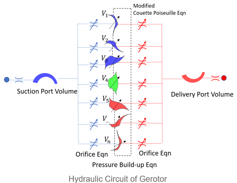
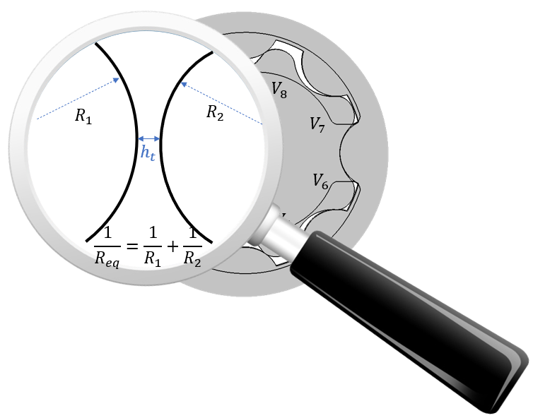
The modified Couette-Poiseuille equation is implemented in MeshingGears function. It takes into account the contact forces as well as tooth tip leakages.
ToothTip.emplace_back(
    dictInOut, //!< input/output dictionary (for adding printable features)
    "ToothTip_" + std::to_string(i + 1),//!< Name of features for adding dictionary features
    "Tooth Tip", //!< Brief description of feature for output list
    TSV[i],//!< Connected inlet volume (lagging angular volume : angin < angout for thetaHatDir>0)
    TSV[prv],//!< Connected outlet volume (leading angular volume : angin < angout for thetaHatDir>0)
    Geometry,//!< Geometry table
    FluidProps, //!< Fluid props table
    Position, //!< Gear position node for adding shear force
    i* TWO_PI / z, //!< initial angle of the Gap
    faceWidth,      //!< face width of the gear [constant]
    driveGear,      //!< Body, primeMover
    driveGear,      //!< Body 0
    drivenGear, //!< Body 1
    -1,                     //!< Gives the sign of angle_outlet - angle_inlet
    2. / ((1.0 - PoissonDrive * PoissonDrive) / EDrive + (1.0 - PoissonDriven * PoissonDriven) / EDriven), //!< Effective Young's Modulus
    coefRestitution, //!< Coefficient of Restitution
    0., 0.,         //!< x,y coordinate of Center of Gear 0 from geometry Table
    -ecc, 0.,               //!< x,y coordinate of Center of Gear 1 from geometry Table
    0.,                             //!< location of the gap in z direction
    ttip_points_indices, //!< All the Tooth Tip point features,
    1., // factor of rotation speed of OmegaZbody0/OmegaZ(primMover) from geometry Table
    (z - 1.) / z, // factor of rotation speed of OmegaZbody1/OmegaZ(primMover) from geometry Table
    isSphericalContact, // if spherical contact,  kx^n, where n = 1.5
    deltaDotMinusLim //!< Limiting impact velocity
);
//Add the node to the system of equations
Sys.storeNode(ToothTip[i]);
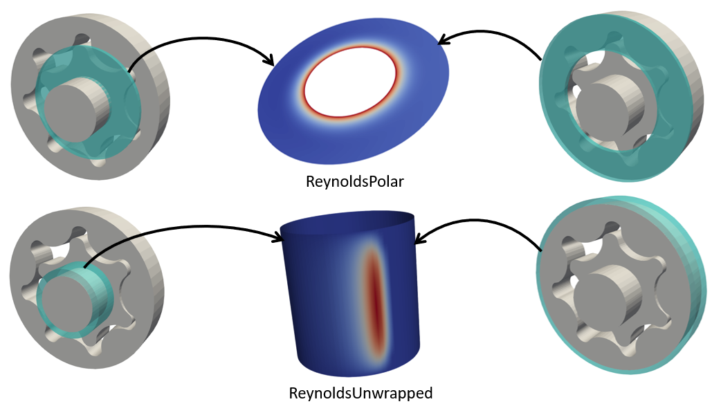
This with the addition of ReynoldsUnwrapped and ReynoldsPolar for journal bearings and lateral films constitute a complete Gerotor Model.
inputDict Definition
The final step before you can simulate the Gerotor is to define variables in the inputDict. To see a completed list of necessary inputs and their explanations go to Gerotor inputDict Definition.