AVAS
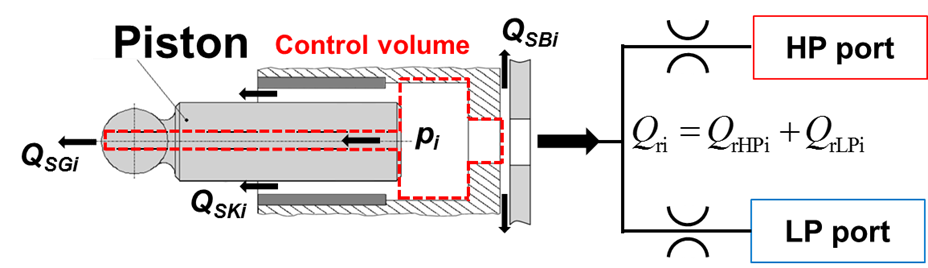
The Automated Valve Plate Area Search (AVAS) utility aids in analysis of axial piston machines (APMs). When modeling APMs, the orifice equation is used to approximate the flow into and out of the displacement chambers. However, this equation relies on an estimate of the area through which the flow moves.
AVAS solves for minimum area of cross-section of the fluid geometry normal to several flow streamlines for every desired step angle in a complete shaft revolution. The minimum area of cross section across the different streamlines represents the smallest opening between the displacement chamber and the high or low pressure ports. These minimum opening areas are critical to the calculation of the port flows as shown in the figure below.
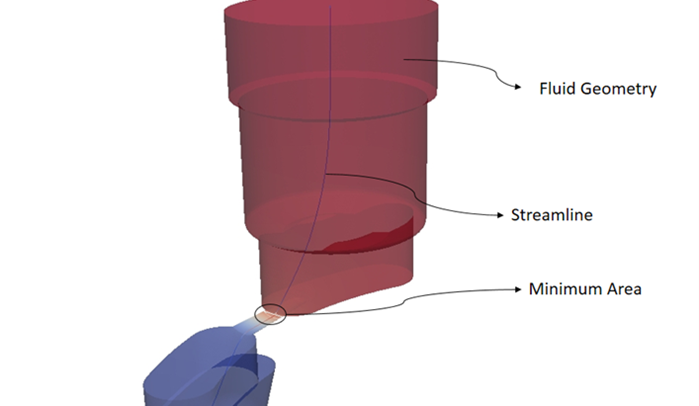
To approximate the minimum opening area, AVAS uses a potential flow solver to calculate streamlines between the displacement chamber and inlet/outlet ports of the APM. The minimum opening area of flow is estimated as the minimum cross-sectional area normal to the streamline. The following figure shows a sample output from the AVAS software which depicts an example of such a streamline.
AVAS Installation
Contact the Maha Fluid Power Research Center to obtain the AVAS tool.
AVAS is used through the command line. The installation steps are as follows:
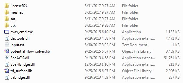
Copy the area file generation folder containing required libraries and the compiled executable from the repository. The sample folder structure is shown in the figure below
Run
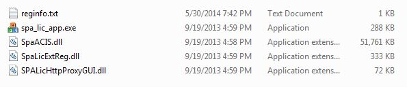
license24/spa_lic_app.exeas an administrator. In the “Third Party Component Registration” window, fill out the “Application” tab with the information in the information fromlicense24/reginfo.txt.

The contents of license24/reginfo.txt are shown in the figure below:
Finally, clicking the “Register” button completes the AVAS installation procedure.
CAD Preprocessing
The fluid geometry has to be predefined for the AVAS to function. The required steps to generate the fluid volume are discussed below.
Note
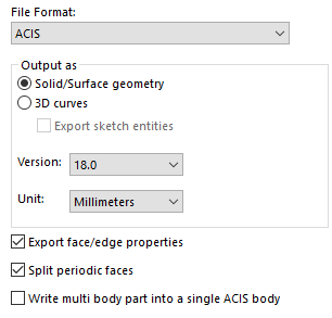
The CAD software used for this manual is SolidWorks, although any CAD package capable of handling STEP and SAT files can be used. If using SolidWorks, SAT files should be saved in Version 18.0. This can be done from the “Options” tab when saving the CAD file to SAT format as shown in the figure below.
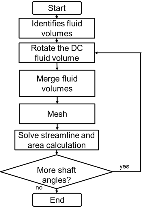
The flowchart below shows the preprocessing steps to prepare geometry for AVAS.
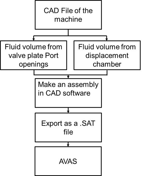
Expanding on the flowchart above, the following steps should be performed to preprocess CAD geometry for AVAS.
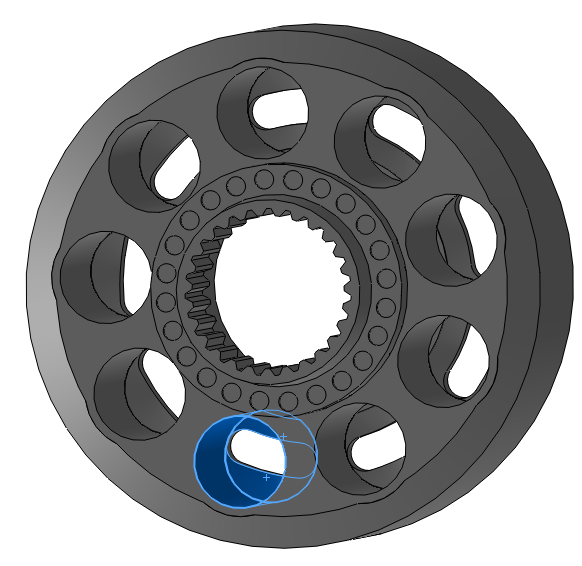
Import the STEP file of the machine into your chosen CAD software. It is important to separate the two required parts for this model: the cylinder block and the valve plate-end case assembly. First, save the cylinder block CAD file, which should look similar to the figure below. A single displacement chamber is highlighted in the cylinder block CAD.
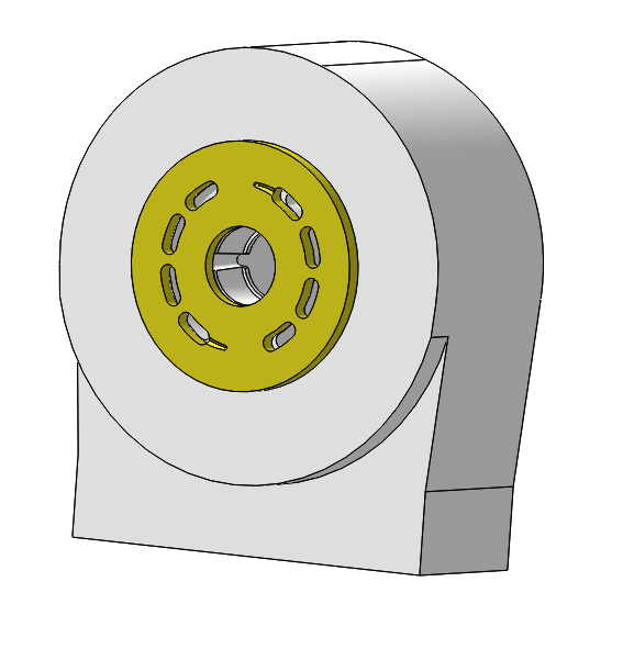
Next, save the valve plate CAD file. This file can include the end case if available below but is not mandatory. The figure demonstrates the valve block CAD, including the end case. You can also simplify the geometry of the ports in the end case; AVAS only focuses on the minimum cross-sectional area between the displacement chamber and the valve plate openings.
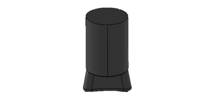
Opening the cylinder block CAD file, extract the fluid volumes for a single displacement chamber (only one is analyzed since the APM operation is periodic so the other chambers will follow the same area openings). The following figure shows the fluid volume in a single displacement chamber.
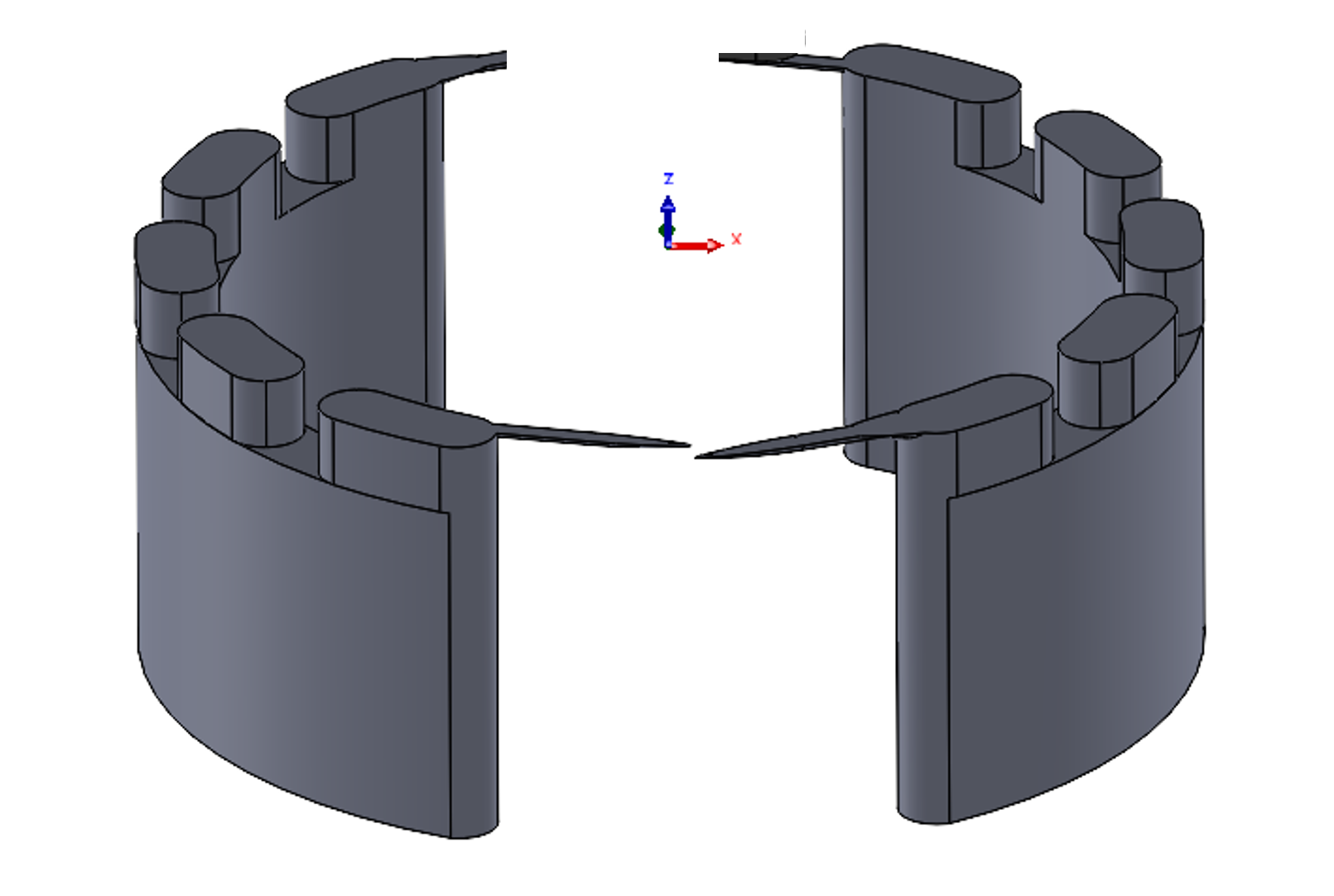
Opening the valve plate-end case CAD file, extract the fluid volumes of the high- and low-pressure ports. The valve plate and end case are assembled together because these bodies remain stationary throughout the operation of the machine. The fluid geometry must include the fluid through the valve plate and the end case including the port volumes. The following figure shows a representative fluid volume of the valve plate-end case assembly.
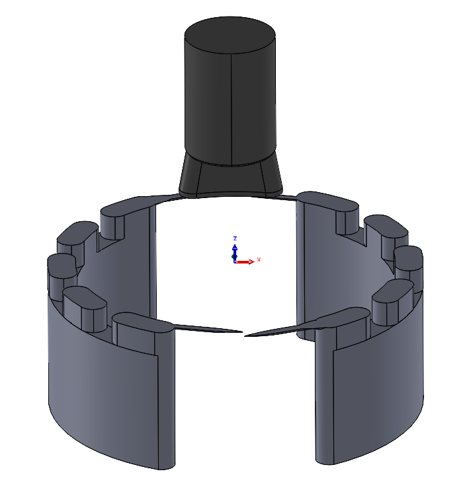
In a new CAD file, assemble the fluid volumes from Steps 3-4. Place the displacement chamber fluid volume at the outer dead center position (\(\varphi = 0\)), with the displacement chamber volume on the \(+z\) size and the port opening volumes in \(-z\) direction.
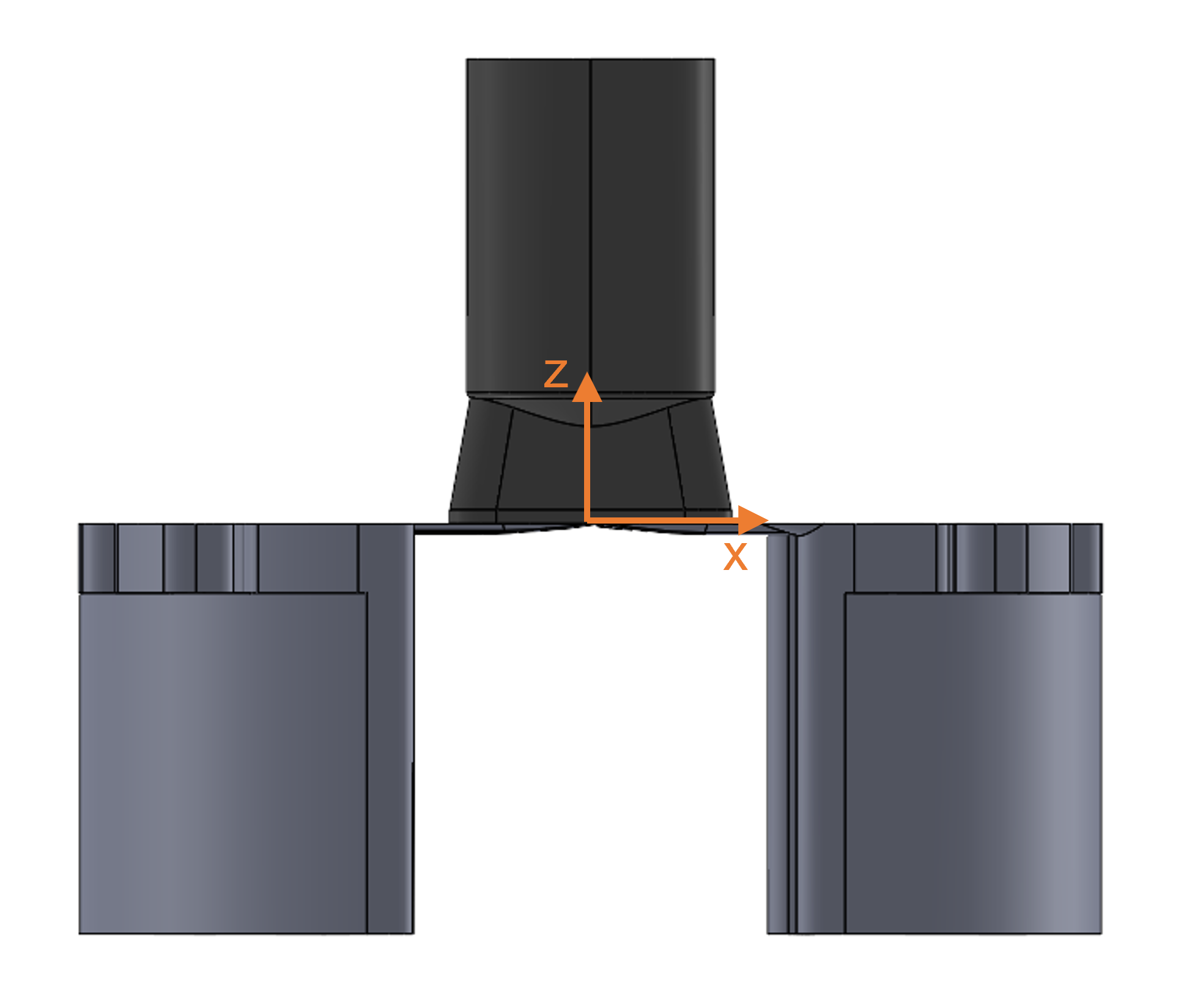
Export the CAD file as a SAT file and save it in the AVAS folder. Ensure that the final CAD file exactly has three solid bodies corresponding to the (1) displacement chamber, (2) high-pressure port, and (3) low-pressure port. The assembly must be aligned such that following conventions are met (see figure below):
The shaft axis must correspond to the \(z\) axis.
The origin must be located at the intersection of the shaft axis and the plane of intersection of the fluid volumes.
AVAS Inputs
AVAS requires geometry, tolerances, meshing parameters, shaft angular span of interest and port selection as inputs. The input parameters in this section are required for the computation and should be stored in the input.txt file.
It is recommended that users adjust parameters like step limits, step size, port selection, direction of rotation, mesh parameters, and streamline parameters, but the mesh parameters are advised to be kept as their default values.
The following figure shows the convention in the coordinate system depicting the direction of rotation of the shaft.

The following list explains each of the inputs and recommended values.
- Direction of rotation
The selection determines the direction of rotation of the displacement chamber volume with respect to the \(+z\) axis. Set to 1 for counterclockwise rotation or -1 for clockwise rotation
- File name
File path and name of the SAT file containing the fluid volumes assembled in the Preprocessing section
- Fine edge size
Keep the default value of 0.01 mm
Unit: mm
- Initial translation of DC
In the CAD file, the displacement chamber (DC) opening and the port opening are on the same level along the \(+z\) axis. However, the tool relies on moving the DC along the \(-z\) axis to help with the volume intersection. The recommended value for the translation of the DC volume is -0.1 mm
Unit: mm
- Number of streamline points
This number specifies the number of points used on the streamline to evaluate the areas along the streamline. Keep the default value of 100000.
- Port selection
The selection determines which port is solved along the \(x\) axis. Set to 1 to solve the port along the \(+x\) axis. Set to -1 to solve the port along the \(-x\) axis
- Solid mesh growth rate
Keep the default value of 4
- Solid mesh size
Keep the default value of 0.5 mm
Unit: mm
- Start shaft angle
Initial shaft angle to obtain the minimum area cross-section. The angle should be initialized a few degrees ahead of the actual geometrical angle where the displacement chamber starts opening to the ports. In the zone of no volume intersection, the tool will not run any potential flow problem and skip the steps automatically
Unit: deg
- Step size
The angular step to be taken between the Start shaft angle and Stop shaft angle. This specifies the resolution of the area file generated. It is recommended to have a finer resolution of 0.1 degrees in predicting area openings on a valve plate groove to predict the pressurization and depressurization trends accurately. The recommended step size elsewhere is 0.5 deg. Therefore, it is often required to run separate AVAS runs with appropriate step sizes to accurately capture the groove opening geometries. A final post-processing of the area predicted will allow to interpolate the data if required
Unit: deg
- Stop shaft angle
Final shaft angle to obtain the minimum area cross-section. The angle should be specified a few degrees after of the actual geometrical angle where the displacement chamber ceases to open to the specified port solved
Unit: deg
- Streamline step size
Keep the default value of 0.02
- Surface mesh size
Keep the default value of 0.4 mm
Unit: mm
- Write mesh/vtk files
This selection enables or disables the writing of mesh and VTK files out for each angular step solved by AVAS. It is recommended to keep the default selection of 1 (enables writing mesh and VTK files)
Running AVAS
To run AVAS, call avas_cmd.exe in the AVAS working directory from the command line as shown below:

First, the two port fluid volumes and the DC fluid volume to be evaluated are identified. When AVAS runs, it rotates the displacement chamber about the \(+z\) axis of the CAD geometry. At each angle, it solves a potential flow problem, calculates the minimum cross-sectional area between the displacement chamber and the high- and low-pressure ports, and outputs it to a file named area.txt (described in the AVAS Outputs section). The flowchart below summarizes the steps performed when AVAS runs.
AVAS Outputs
AVAS outputs several files:
Area text
area.txtfilevtk files
meshesfilessatfiles
The outputted text file has six columns: shaft angle, min_area_cad, min_area_mesh, max_streamline_v, max_mesh_v2, and max_mesh_cells_v2 as shown below.
area.txt%deg min_area_cad min_area_mesh max_streamline_V max_mesh_V2 max_mesh_cells_V2
346 0 4.23934 38.6148 236.044 200.823
346.5 0 3.47561 46.6561 264.848 220.051
347 0 2.95072 57.9977 311.161 241.51
347.5 0 2.50406 72.5074 355.938 280.982
The first and third column of the text file corresponds to the shaft angle %deg and the minimum area min_area_mesh cross-section along the streamline at that position. These two columns are essential to make an area file for an APM simulation. The other four columns are only important for AVAS developers and are not explained in detail.
The vtk, sat, and meshes are written for each angular step but are not essential for generating the area file or using area files for an APM simulation. The VTK files are crucial to visualize the volumes, mesh, area and streamline at each angular step. These files can be visualized using ParaView. The sat and meshes files are only important for AVAS developers and are not discussed in depth. The Write mesh/vtk files input can be turned off to avoid printing of these files.
Postprocessing AVAS Outputs
To use the area file in Multics, area outputs for every shaft angle are required for both the suction and delivery ports.
When AVAS has completed its analysis, a text file with the area output for different shaft angles is obtained for each of the ports. This data can be plotted using other software applications like Microsoft Excel or MATLAB.
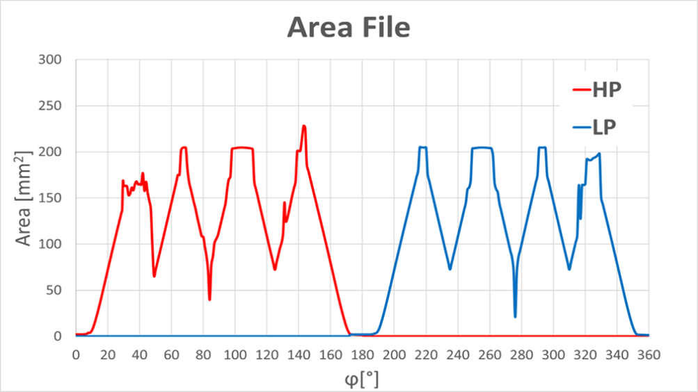
Often, as seen in the figure above, the raw area outputs from AVAS fluctuate even after the ports are fully open to the suction or delivery port. When the port is fully open, the area opening is no longer an orifice and therefore, it is not recommended to use the raw areas predicted by AVAS. After a point the area opening is considered large enough (around 29 degrees for the HP port in the above figure) that area variations no longer have significant impacts on the net pump characteristics. Hence a reasonable approximation of a constant area is assumed in these angles with large area openings (typically close to the maximum area predicted). The approximated area for both the ports for the above area openings can be shown below.
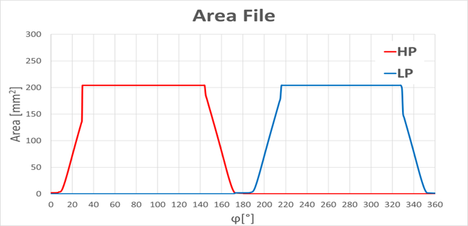
These areas of the port along with the corresponding shaft angle form the basis of creating a area file used for Multics. This file takes the form of a one-dimensional Lookup Table with four outputs: the inlet orifice area and hydraulic diameter and the outlet orifice area and hydraulic diameter at each shaft angle. The hydraulic diameter, in this case, is the diameter of the circle which has the same area as given by AVAS. An example of this table is given below:
areaTable.txt720 4
deg: 0 0.5
-: 1 1
mm^2: 1.142857143 1.238095238 1.333333333 1.428571429 1.523809524 ... #Inlet orifice area
mm: 1.20628807 1.255544431 1.302940032 1.348671063 1.392901484 ... #Inlet orifice hydraulic diameter
mm^2: 1.142857143 1.047619048 0.952380952 0.857142857 0.761904762 ... #Outlet orifice area
mm: 1.20628807 1.154932898 1.101185311 1.044676113 0.984930085 ... #Outlet orifice hydraulic diameter
Note
There are certain cases when AVAS may fail to predict an area for a particular angle (for example, if the sectioned body intersection is smaller than the distance tolerances or the section splits into separate cross-sections). In such cases, rerun AVAS locally or interpolate it from the neighboring steps. Similarly, the minimum area cross-section predicted can be areas not present on the valve plate surface leading to discontinuous area file prediction. The VTK files can help visualize these cases and help take appropriate remedial measures (simplify or refine CAD).