Influgen
This section of the documentation highlights the basic concept behind influence matrix generation for calculation of solid body deformation. Mesh file generation using ANSYS will be explained followed by generation and visualization of the influence matrix.
What Is an Influence Matrix?
Simulation of fluid structure interaction is an important component in a simulation of a positive displacement machine. Deformation of solid bodies due to pressure loading acting on them is a type of fluid structure interaction that can be modeled using Multics. Influence matrix operator, under the assumption that the material of the bounding bodies is uniform and isotropic, with small strain, can be used to model linear elastic deformation of these bodies. More information regarding the theory behind influence matrix operator can be found in [Pelosi2009].
How Multics Evaluates Deformation of Bodies using an Influence Matrix
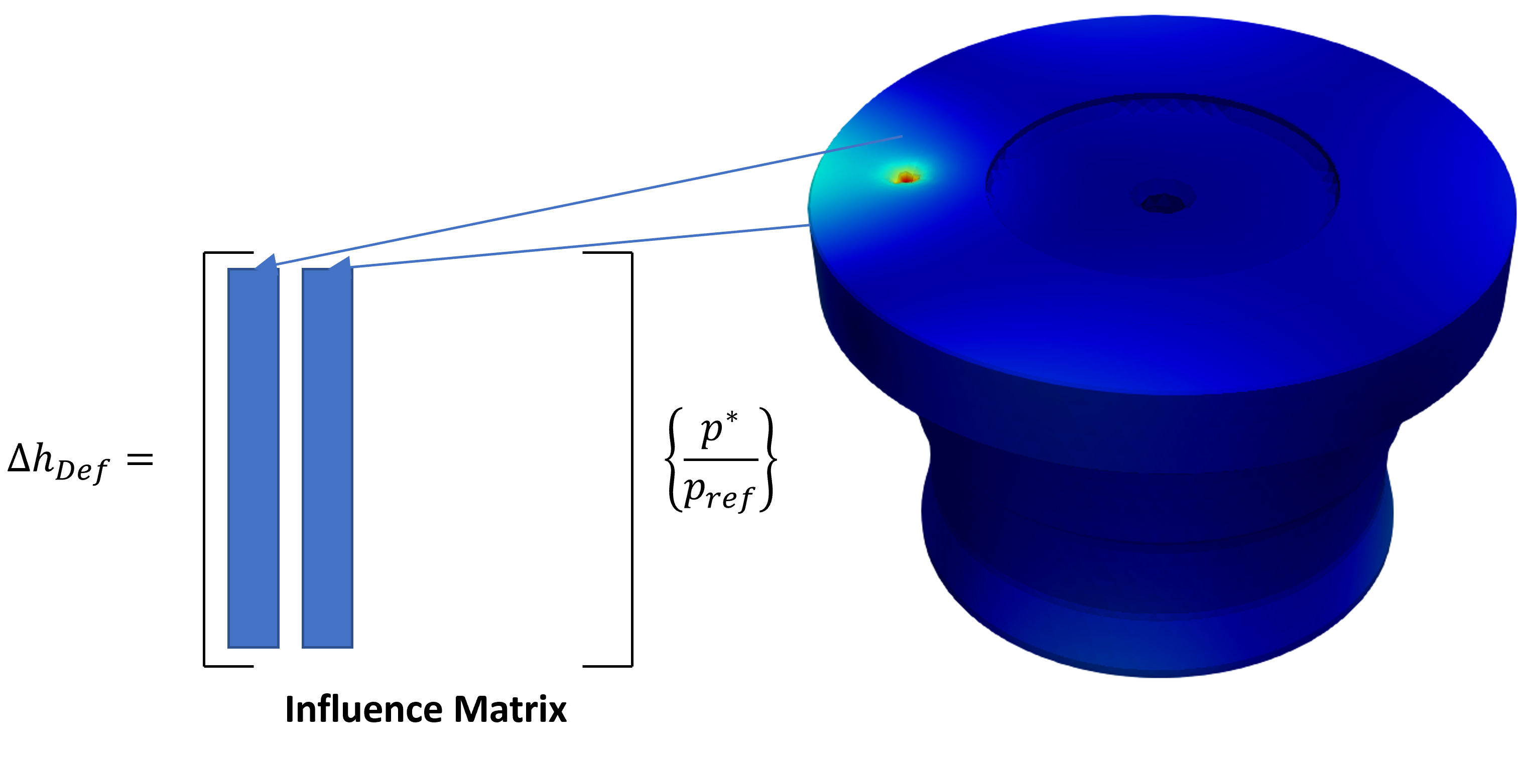
To explain briefly, the influence matrix operator stores the information of deformation of each node of the body under action of a reference pressure applied at a certain location. The influence “matrix” thus generated is given as an input to Multics, where the deformations of each node are scaled based on actual operating pressures to obtain final deformation vector at each node which can be further used by Multics. This process is repeated for all faces of the body where pressure loads are acting. The concept is shown in the figure below.
How to Generate an Influence Matrix using Influgen
Generation of influence matrix is done using Influgen, an in-house software. A mesh file with .cdb or .inp extension must be provided as input to Influgen. The process of mesh file generation using ANSYS is outlined below.
Mesh File Generation Using ANSYS
Workbench Model
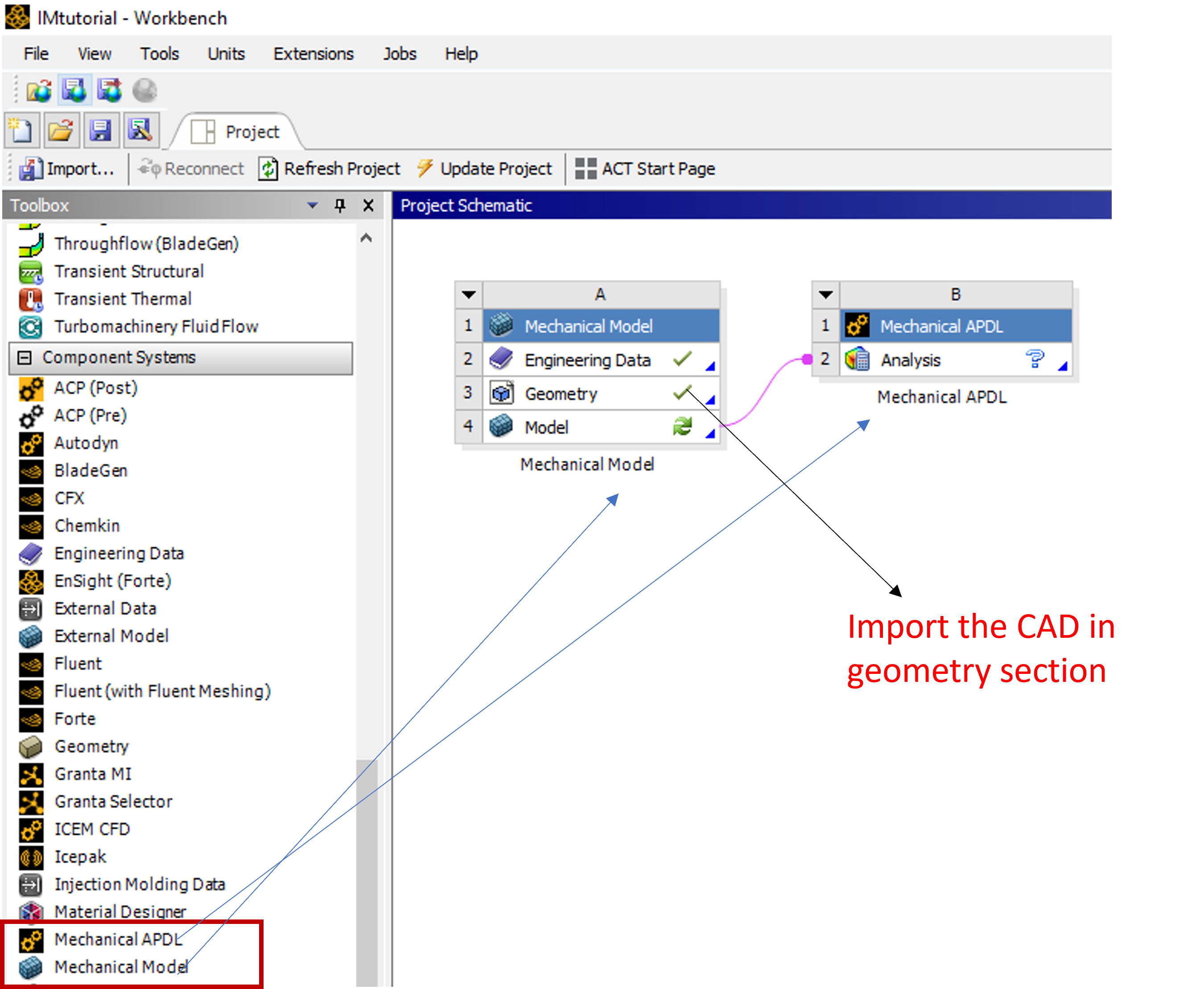
The first step of mesh file generation is setting up ANSYS workbench model. For the same, drag Mechanical Model and Mechanical APDL component systems to the workspace. A CAD of the body is required to start the mesh generation process which will be imported in mechanical model’s geometry section as shown.
Coordinate System
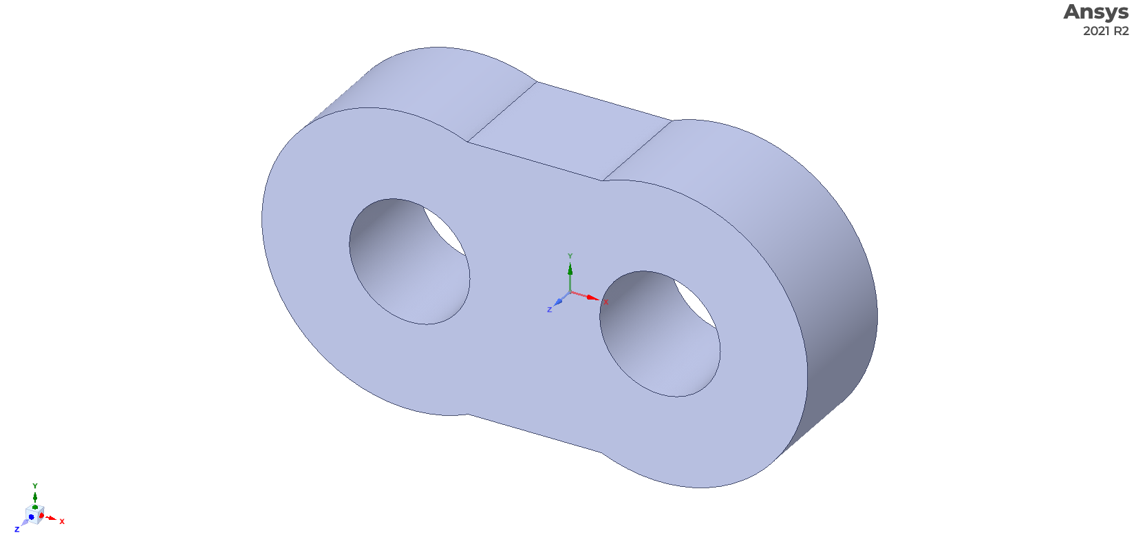
To simplify the process of implementation of influence matrix deformation in Multics, it is recommended to ensure that the coordinate system of the CAD follows the same origin and coordination system orientation convention as defined by the corresponding Multics object. As an example, for the lateral bushing of an external gear machine, the origin should be at the geometrical center of the bushing while the orientation of the bushing should be as indicated in the figure.
Two Bodies
If two bodies are being used, the user must open the CAD files in ANSYS SpaceClaim and select the Share Topology option and set it to Share as seen in the figure.
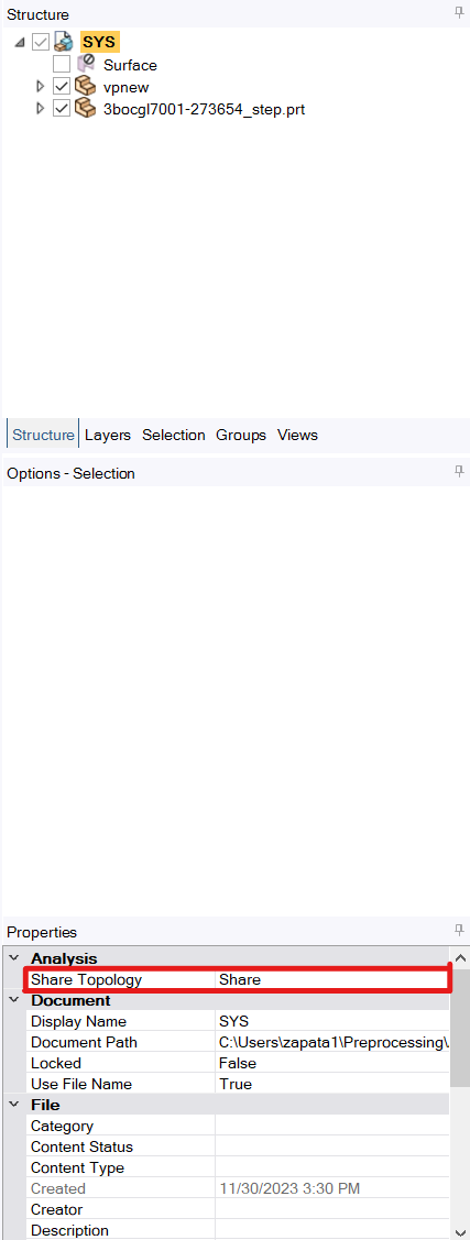
This setting ensures that the generated mesh is shared between bodies and results in a continuous mesh at all boundaries between these bodies.
Warning
The Share Topology setting must be changed for all bodies that will be in the mesh for Influgen to work correctly. If the nodes of the mesh are not coincident with each other on surfaces that are touching, then the topology has not been shared correctly. Return to this step and ensure all bodies have Share Topology turned to Share.
Mesh Settings
To generate the mesh following steps are followed.
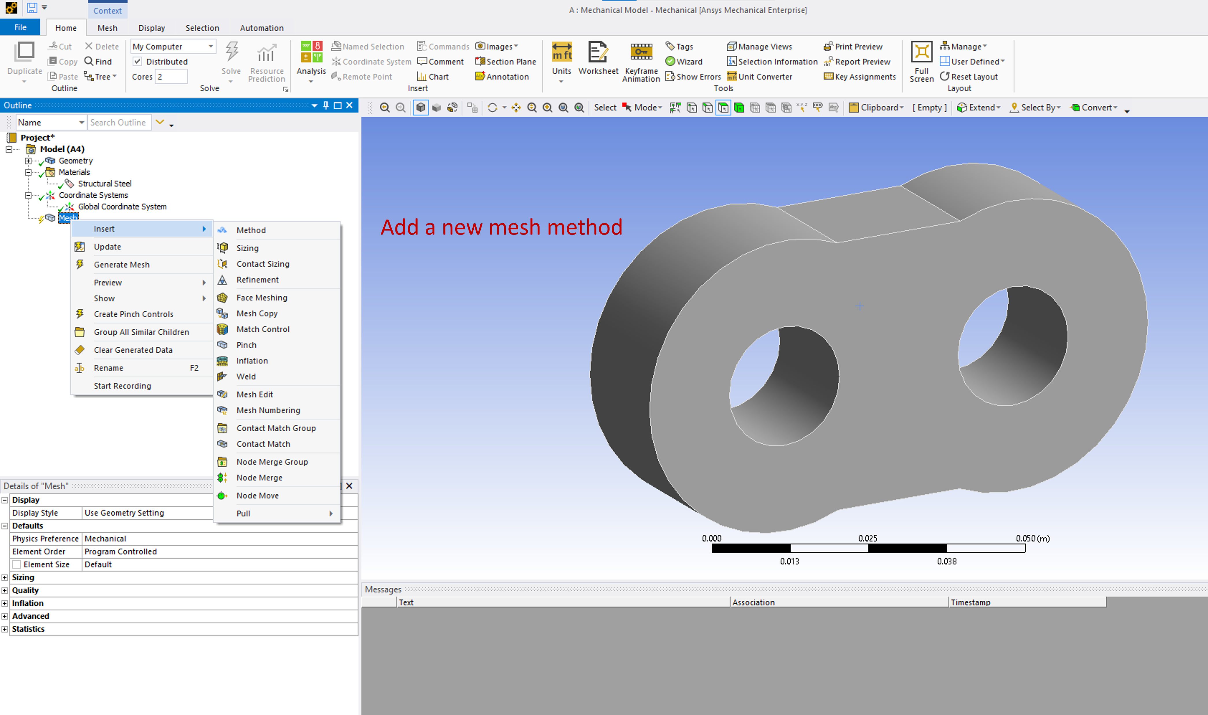
Open the mechanical model editor and insert a new mesh method as shown below.
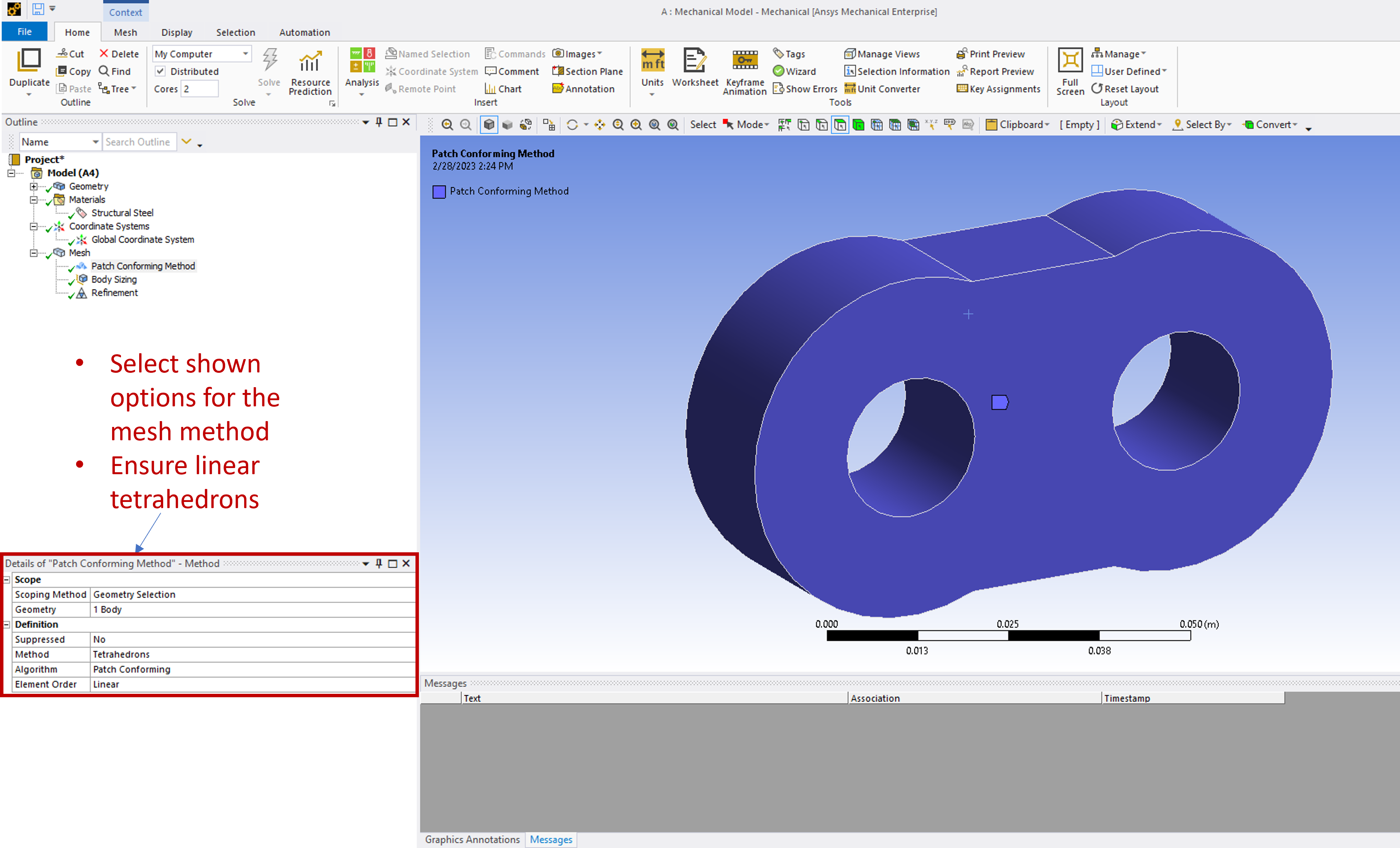
Add a new tetrahedron mesh with linear elements and patch conforming algorithm for the selected body.
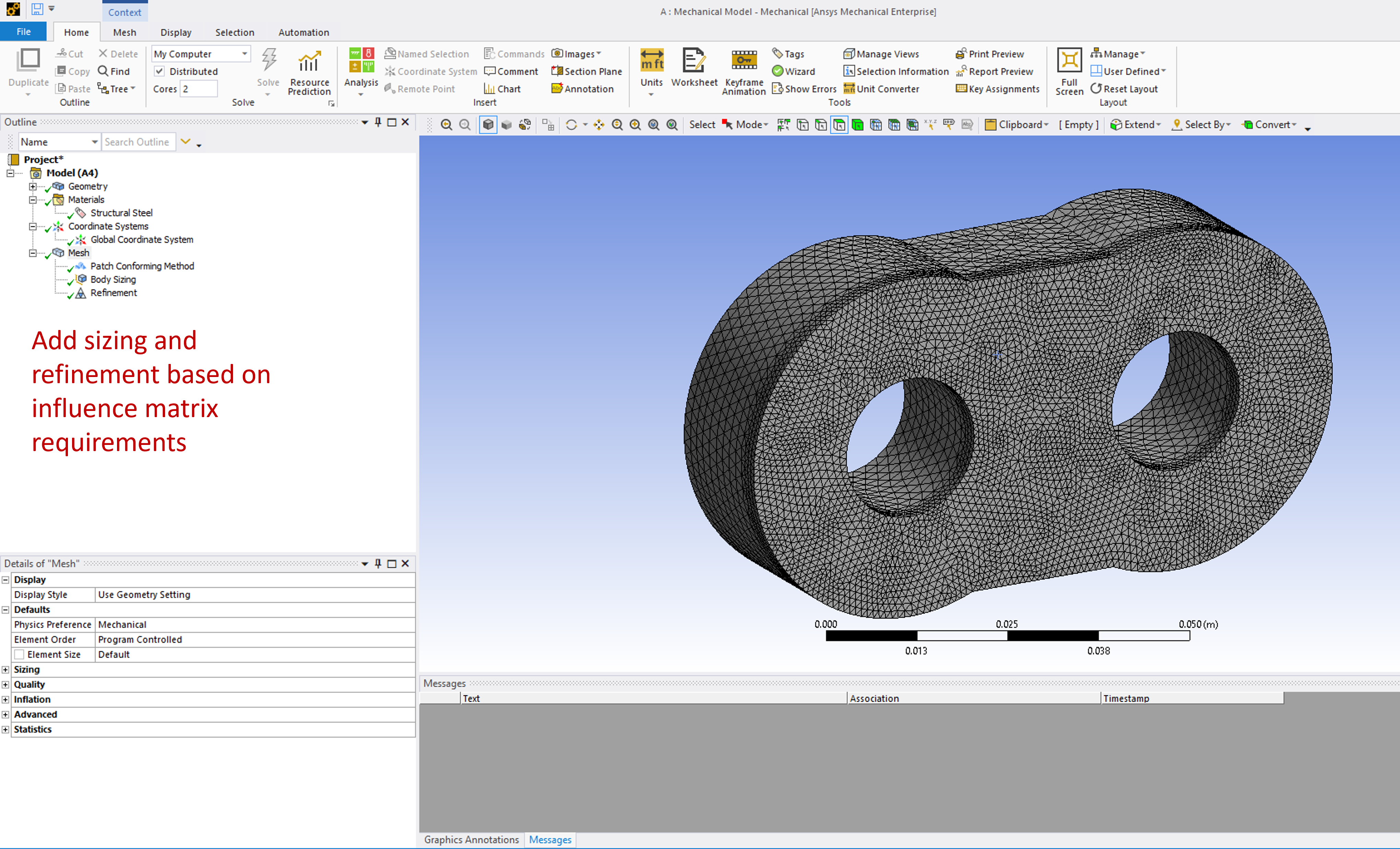
Adjust the size of the elements. Add refinements to the mesh in the regions where lubricating films are present if required. It is recommended that the number of elements at the lubricating interface approximately similar to the number of elements of the corresponding Reynolds film in Multics.
Named Set Selections
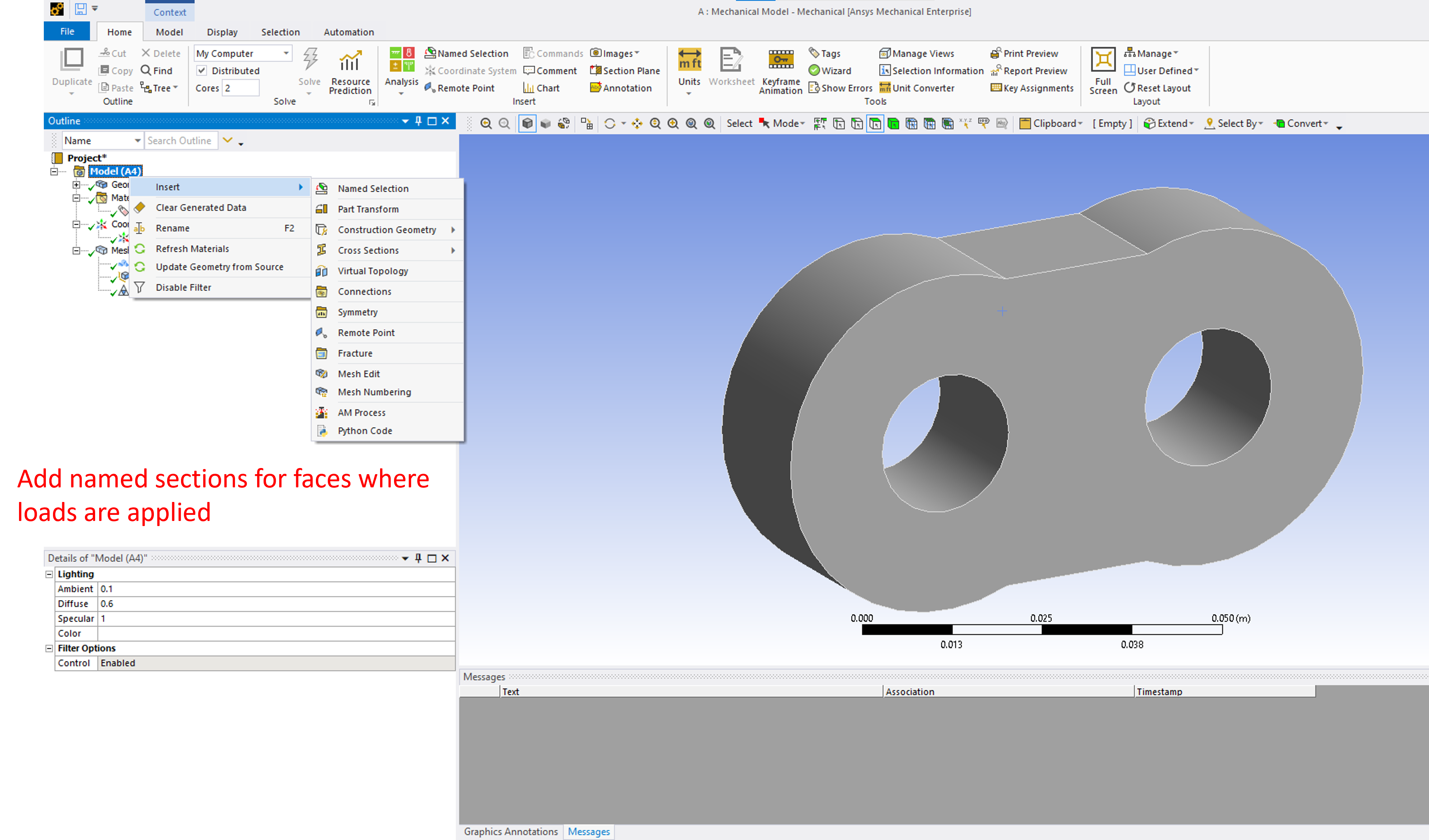
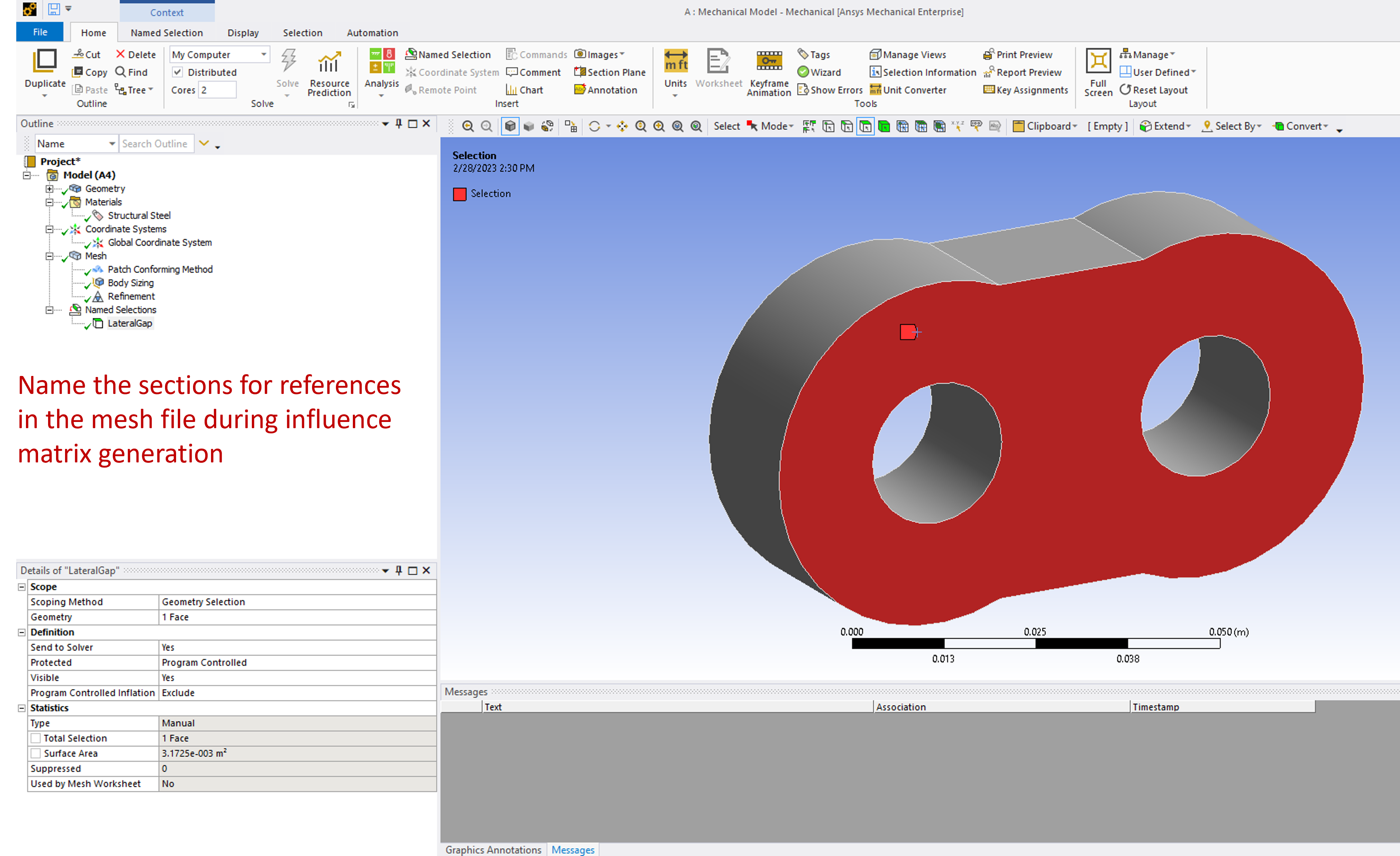
During Multics simulation, the operating pressures and loads at different interfaces are considered for deformation calculations. The information regarding locations of application of these loads is conveyed in the influence matrix using named selections to Multics. Named selections must be added to all faces where loads are acting as shown below. Difference named selections must be selected for faces where lubricating interfaces are present. Along with faces where loads are acting, faces where a constraint or boundary condition is applied must also be included under named selections.
Add a new named selection to the model.
Select the appropriate faces and give a label or name to the named selection. This name is also used in Influgen while generating influence matrix.
Exporting Files
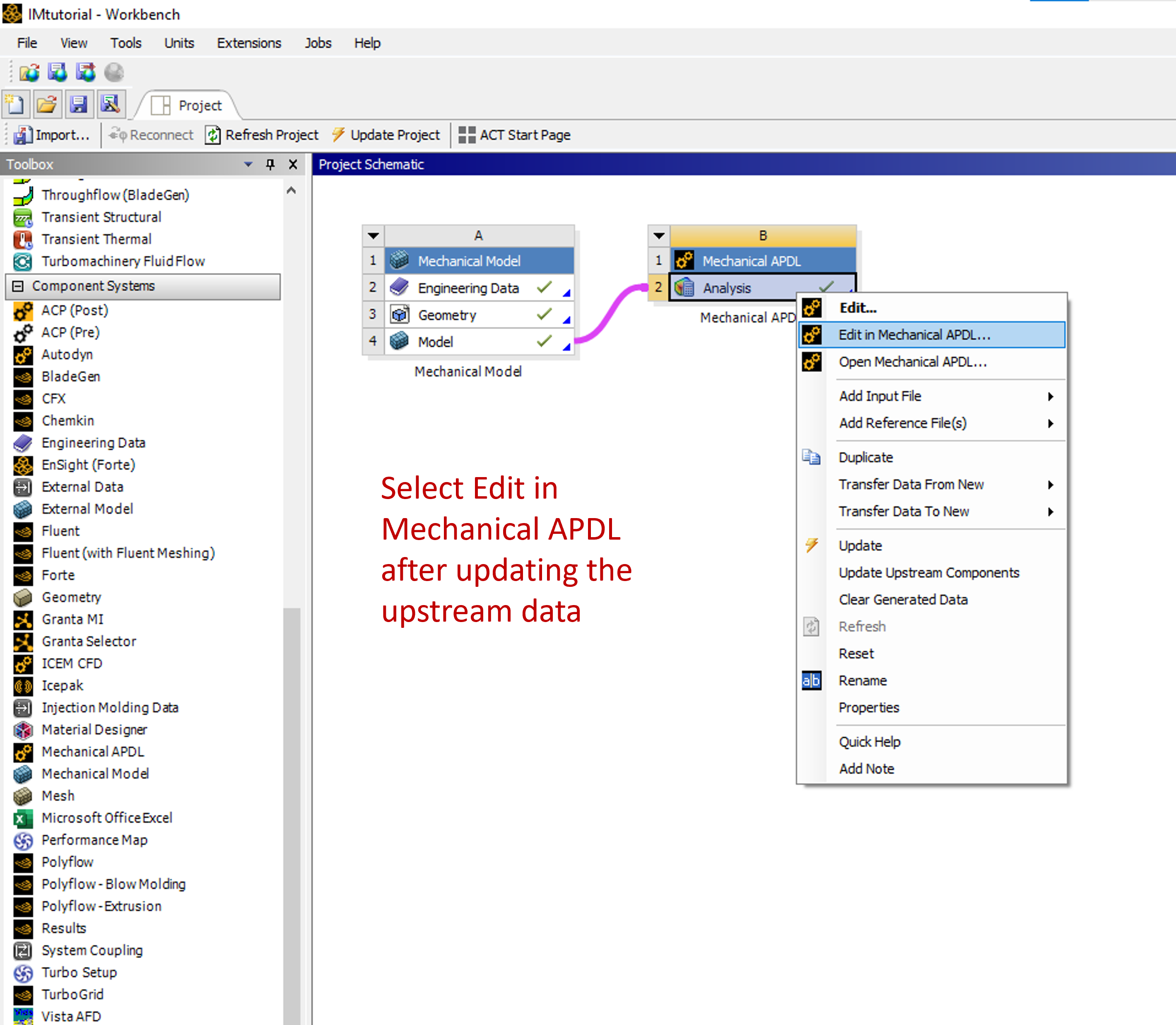
The mesh file in .cdb format is exported from ANSYS workbench. Mechanical APDL component system is used for the same as shown.
Select edit with mechanical APDL in ANSYS workbench after updating upstream information.
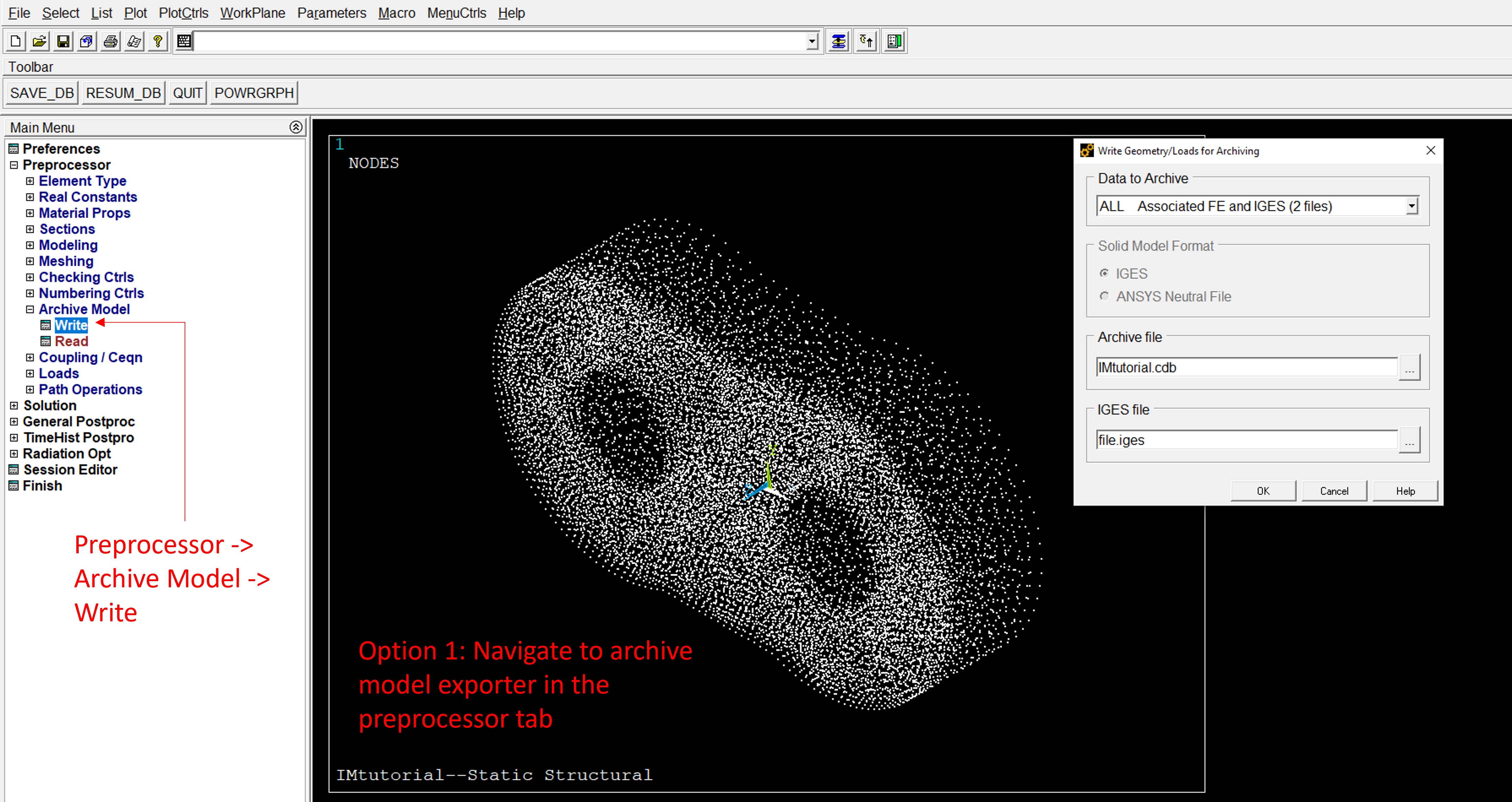
First option is to export using preprocessor tab as shown.
Alternatively, a command line input can be given to store the mesh using ANSYS APDL command-line. Use the command below or as shown in the figure.
CDWRITE,CM,NAMEOFFILE,cdb
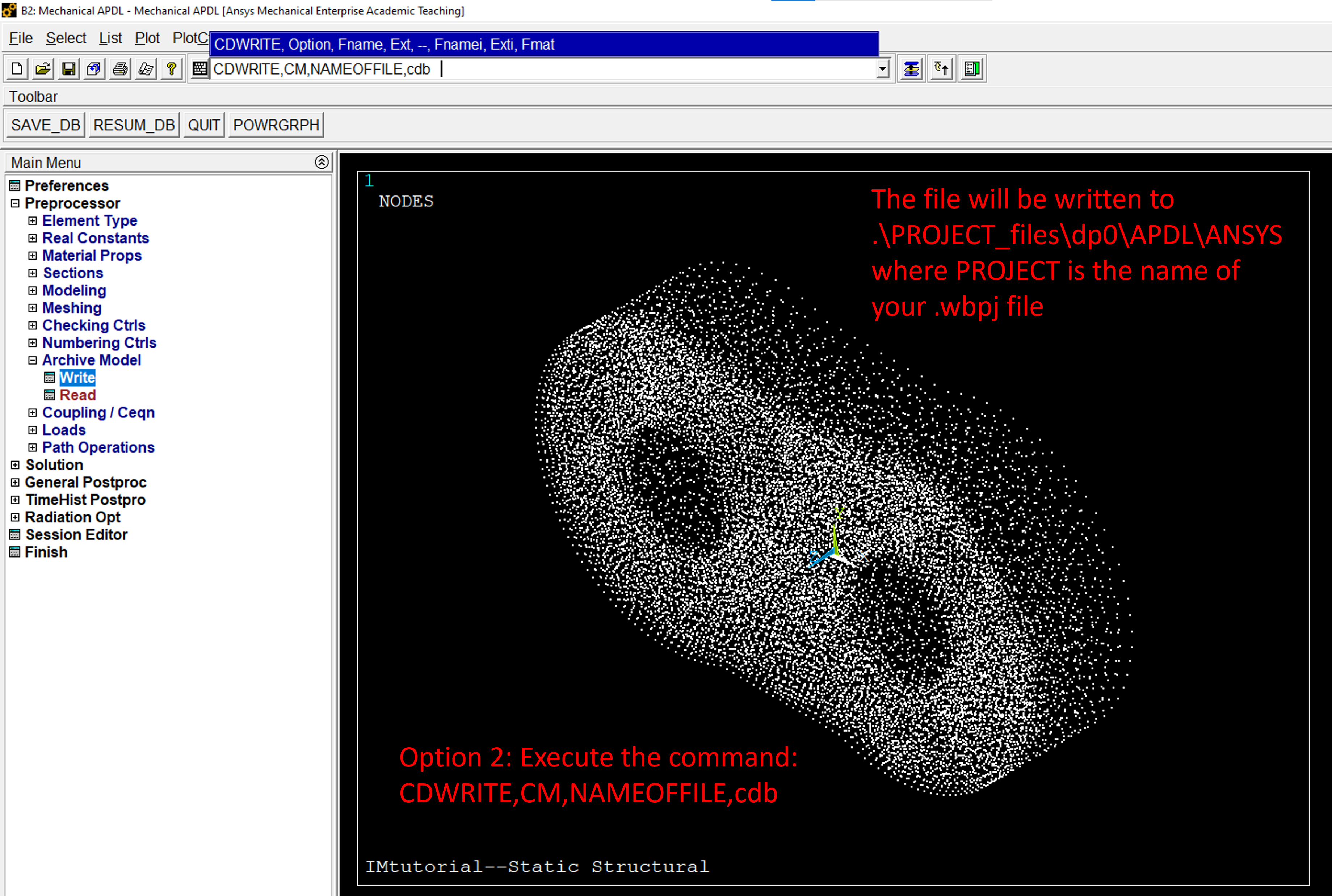
The exported mesh file will be stored at following location.
+-- Project Folder
|   +-- PROJECT_FILES
|   |   +-- dp0
|   |   |   +-- APDL
|   |   |   |   +-- ANSYS
|   |   |   |   |   +-- NAMEOFFILE.cdb
Influgen Configuration
File Organization
The influence matrix generation directory structure should follow configuration as shown.
+-- Project Folder
|   +-- input
|   |   +-- input.txt
|   |   +-- NAMEOFFILE.cdb
|   +-- vtk
|   |   +-- Output VTK Files
|   +-- influgen.exe
|   +-- intel 'mkl' dll files required
Inputs and Constraints
The anatomy of an example input.txt file is shown below.
// ------------------------- General information --------------------------- //

section general

// Analysis name
pump        Influgen_tutorial
meshFile    ./input/examplemesh.cdb

// Mesh dimensions [m or mm]
dimension    m

// Inertia relief
inrel    1

// Allowable memory
ram    3000

// Option to take only specified elsets. Default is all if this field not given
elsets 1 body1

endsection

// ------------------------------- Materials ------------------------------- //

section material

    name   Material1
    E      70e9  // [Pa]
    nu     0.3   // []
    rho    2700  // [kg/m^3]
    sets   1     body1 // volume sets using this material

endsection

// ------------------------------- Constraints ----------------------------- //

section constraint

    //set const //set to apply to
    //x 1 //fixed x
    //y 1 //fixed y
    //z 1 //fixed z

endsection
Three sections of the inputfile.txt are explained below.
Section 1: General Information
This section has following information.
Analysis name
Location of the mesh file with respect to the executable directory
Dimensions of the mesh file (same as dimensions of the ANSYS mechanical model)
Flag indicating if inertia relief constraint is considered or not
RAM used for influence matrix generation
Element sets considered. Bodies with different materials are assigned different sets. This visualization can be done using VTK files printed using Influgen as described in Visualization of Influence Matrix.
Section 2: Materials
This section assigns material properties to different element sets. Following inputs are considered.
Name of the material
Young’s modulus
Poisson ratio
Density
Set to which this material is assigned
For an influence matrix with multiple materials, a new material section must be created for each material to be used. The bodies using a material can be specified in the same way, separated by spaces. An example can be seen below.
// ------------------------- General information --------------------------- //

...

// ------------------------------- Materials ------------------------------- //

section material

    name   Material1
    E      75e9  // [Pa]
    nu     0.33   // []
    rho    2760  // [kg/m^3]
    sets   2     body1 body2 // volume sets using this material

endsection

section material

    name   Material2
    E      300e9  // [Pa]
    nu     0.28   // []
    rho    7000  // [kg/m^3]
    sets   1     body3 // volume sets using this material

endsection

// ------------------------------- Constraints ----------------------------- //

...
Section 3: Constraints
This section indicates additional fixed constraints. The named selection to which constraints are applied must be indicated here. If fixed constraint is applied to any location in the mesh, the inertia relief constraint is overwritten and not considered in influence matrix generation.
Name of the set to which constraint is applied
If x DOF is constrained (
0 - Free, 1 - constrained)If y DOF is constrained (
0 - Free, 1 - constrained)If z DOF is constrained (
0 - Free, 1 - constrained)
For an influence matrix with multiple constraints, a new constraint section must be created for each constraint imposed. The format will be the same and the named set must be unique and unused. An example can be seen below.
// ------------------------- General information --------------------------- //

...

// ------------------------------- Materials ------------------------------- //

...

// ------------------------------- Constraints ----------------------------- //

section constraint

    set fixedSet1 //set to apply to
    x 1 //fixed x
    y 1 //fixed y
    z 1 //fixed z

endsection

section constraint

    set fixedSet2 //set to apply to
    x 1 //fixed x
    y 1 //fixed y
    z 1 //fixed z

endsection
Running Influgen
Command-Line Inputs
Influgen executable uses various command line arguments in generation of influence matrix. These arguments are explained below.
Arguments indicating bodies forming a lubricating interface.
-genbody GAP_SUBSETNAME: Indicates that the sign of deformation of gap height of the lubricating interface referenced by named setGAP_SUBSETNAMEwill be handled by Multics.
Warning
Although the first four options exist, -genbody should ALWAYS be used when generating influence matrices in Influgen. Legacy options are available and are listed below, but are not recommended except for experienced users.
Legacy Body options
-topbody GAP_SUBSETNAME: Indicates that the body forming the lubricating interface referenced by named setGAP_SUBSETNAMEis a top body with respect to the respective planar lubricating interface. The deformation of this body has opposite effect on the gap height i.e. the positive deformation of the body would reduce the gap height and negative deformation of this body would increase the gap height.-botbody GAP_SUBSETNAME: Indicates that the body forming the lubricating interface referenced by named setGAP_SUBSETNAMEis a bottom body with respect to the respective planar lubricating interface. The deformation of this body has normal effect on the gap height i.e. the positive deformation of the body would increase the gap height and negative deformation of this body would reduce the gap height.-outerbody GAP_SUBSETNAME: Indicates that the body forming the lubricating interface referenced by named setGAP_SUBSETNAMEis an outer body with respect to the respective cylindrical or unwrapped lubricating interface. The deformation of this body has an opposite effect on the gap height i.e. the positive deformation of the body would reduce the gap height and negative deformation of this body would increase the gap height.-innerbody GAP_SUBSETNAME: Indicates that the body forming the lubricating interface referenced by named setGAP_SUBSETNAMEis an inner body with respect to the respective cylindrical or unwrapped lubricating interface. The deformation of this body has normal effect on the gap height i.e. the positive deformation of the body would increase the gap height and negative deformation of this body would reduce the gap height.
Arguments for managing the outputs of Influgen.
-imset SETNAME: Creates an influence matrix for the nodes indicated for named setSETNAME.-basisset SETNAME: Creates deformation basis vectors for a node set.-vtkset SETNAME: Outputs VTK file for visualization of the named setSETNAMEin the VTK folder.-vtkgap GAP_FACE_ID: Outputs VTK file for visualization of the deformation and loads for a single column of the influence matrix corresponding to theGAP_FACE_ID.-imgap: Creates influence matrix for all lubricating interfaces.-basisgap: Creates deformation basis vectors for lubricating interfaces.-vizvtksets: Outputs VTK file for visualization of undeformed surfaces of defined by all named sets.-vizvtkbodies: Outputs VTK file for visualization of all undeformed bodies present in the mesh file.-inpexport: Outputs the mesh to a.inpfile.
The command line argument for generating the example influence matrix shown in this tutorial is:
influgen.exe -genbody LateralGap -imgap -vtkset LateralGap -vtkset gap -vizvtkbodies -vizvtksets
The above command does the following:
influgen.exe: Calls the Influgen executable to run the software-genbody LateralGap: Indicates that the direction of deformation for the given body will be handled by Multics for lateral gap lubricating interface indicated by named setLateralGap-imgap: Generates influence matrix for all lubricating interfaces present, which is only lateral gap in this case-vtkset LateralGap: Generates a VTK file for visualizing the deformation of body under reference pressure of 100 bar acting at lateral gap interface-vtkset gap: Generates a VTK file for visualizing the deformation of body under reference pressure of 100 bar acting at all lubricating interfaces present-vizvtkbodies: Outputs VTK files for visualization of all undeformed bodies present in the mesh file-vizvtksets: Outputs VTK files for visualization of undeformed surfaces of defined by all named sets
Visualization of Influence Matrices
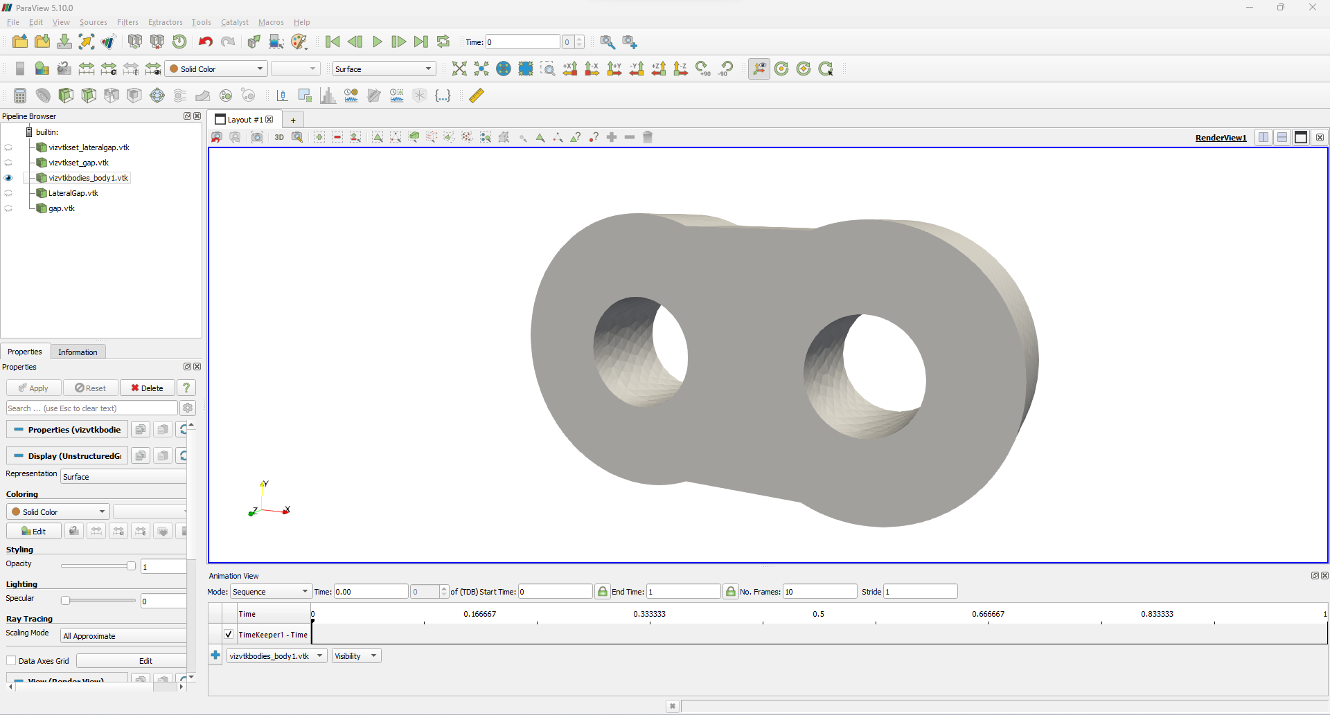
The generated influence matrix can be visualized in the form of output VTK files printed in the VTK folder. There can be different outputs after an Influgen run. The outputs can be visualized using Paraview. The figure below shows the different output files loaded in Paraview for visualization. The visualization can be done for bodies present in the mesh, named sets and influence matrices of different lubricating interfaces. To visualize the VTK of any particular influence matrix, for example, the lateral gap interface in this tutorial, a command of -vtkset SETNAME must be included in the command line argument. The visualization of different components is now shown below.
Visualization of body
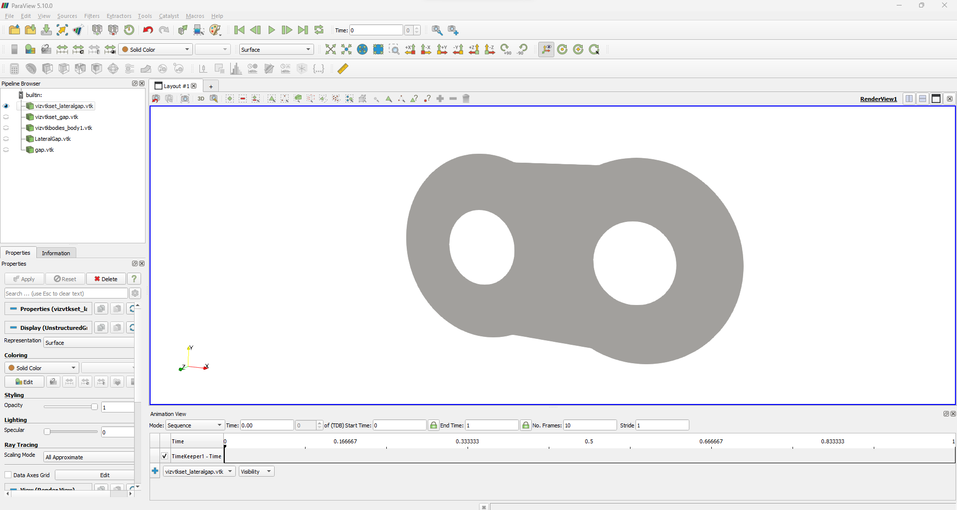
Visualization of named set
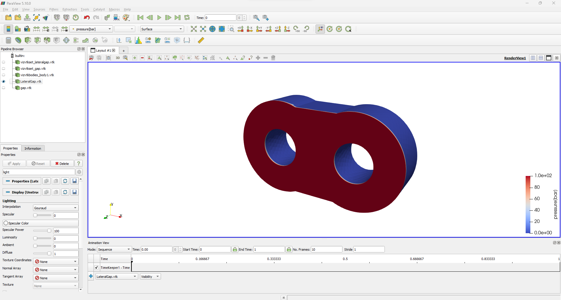
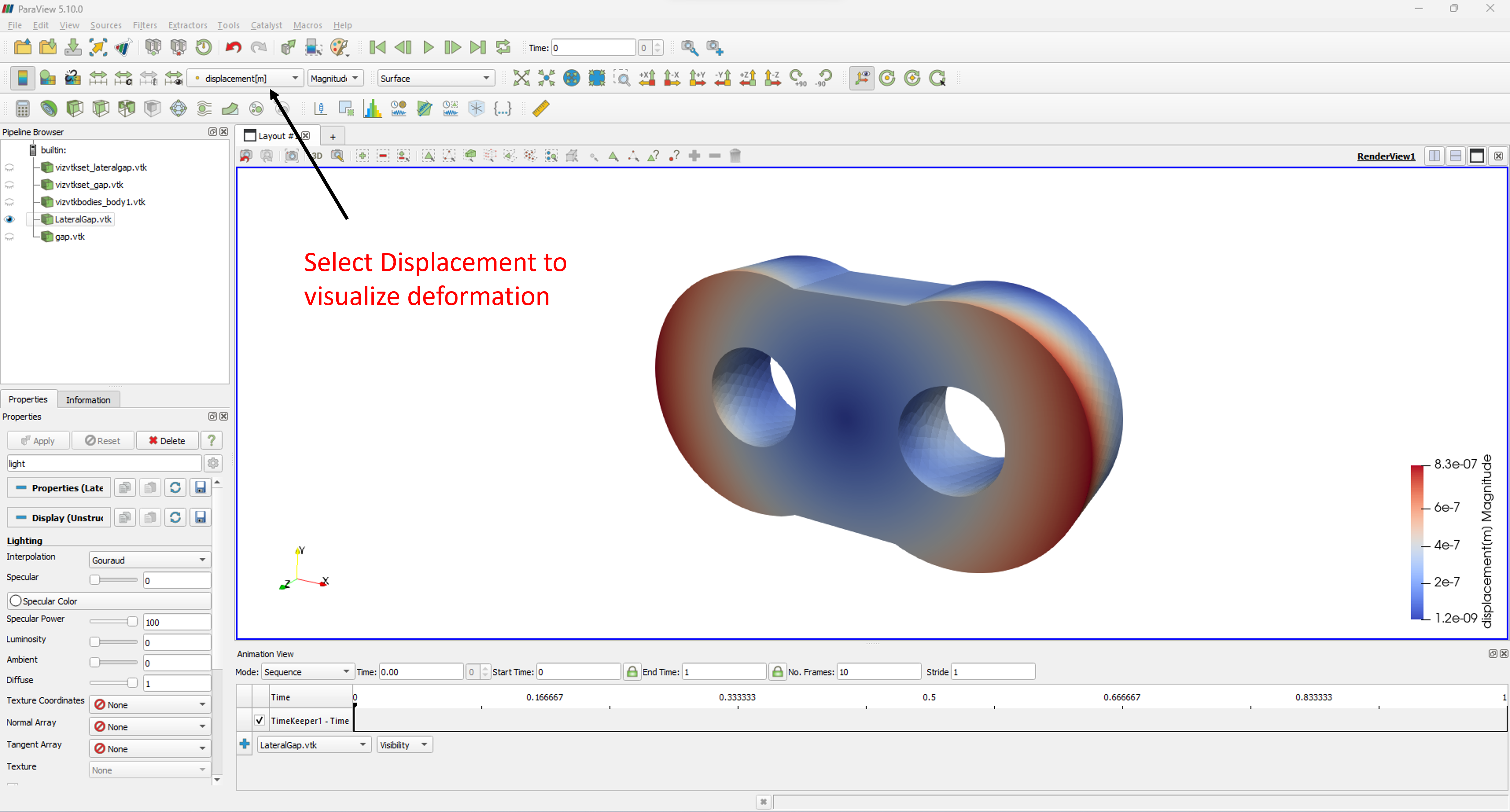
Visualization of deformation under reference pressure using VTK
The reference pressure applied on the lateral gap interface and deformation of the body under inertia relief constraint is shown below.
Influgen Outputs
In this section, the output files generated by running Influgen are explained. After running the above command, the working directory has following structure.
+-- Project Folder
|   +-- input
|   |   +-- input.txt
|   |   +-- NAMEOFFILE.cdb
|   +-- vtk
|   |   +-- Output VTK Files
|   +-- influgen.exe
|   +-- intel 'mkl' dll files required
|   +-- im_gap_lateralgap.bin
|   +-- xyz_nodes_tri.dat
|   +-- xyz_faces_lateralgap.dat
New files generated by Influgen are:
im_gap_lateralgap.bin: Contains the influence matrix which is storing deformation of nodes at lateral gap interface on the body under reference pressure. Similar.binfiles will be generated for all lubricating interfaces as well as faces where constant pressures are acting.xyz_nodes_tri.dat: File indicatingXYZpositions of all nodes with respect to the coordinate system defined while generating the meshxyz_faces_lateralgap.dat: File indicatingXYZpositions of face centers of nodes on the face forming the lateral gap lubricating interface
These output files are then used by Multics to determine the dynamic deformation of bodies during a simulation. The details of how this deformation calculation is included in simulation of individual machines can be found in their respective tutorials.
References
M Pelosi and M Ivantysynova, A novel fluid-structure interaction model for lubricating gaps of piston machines. International WIT Transactions on the Built Environment 105 (2009), pp 13:24.