Internal Gear Machine
This tutorial is for modeling internal gear machines (IGMs).
What is an Internal Gear Machine?
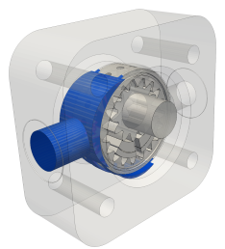
An internal gear machine (IGM) is a type of positive displacement hydraulic machine composed of a gear set consisting of a pinion gear, which meshes with a ring gear. This type of machine can be used as a hydraulic pump when mechanical energy is converted to hydrostatic energy, or as a motor when hydrostatic energy is converted to mechanical energy. IGMs are known to be reliable, resistant to contamination, and quieter compared to other types of positive displacement machines.
IGM Terminology
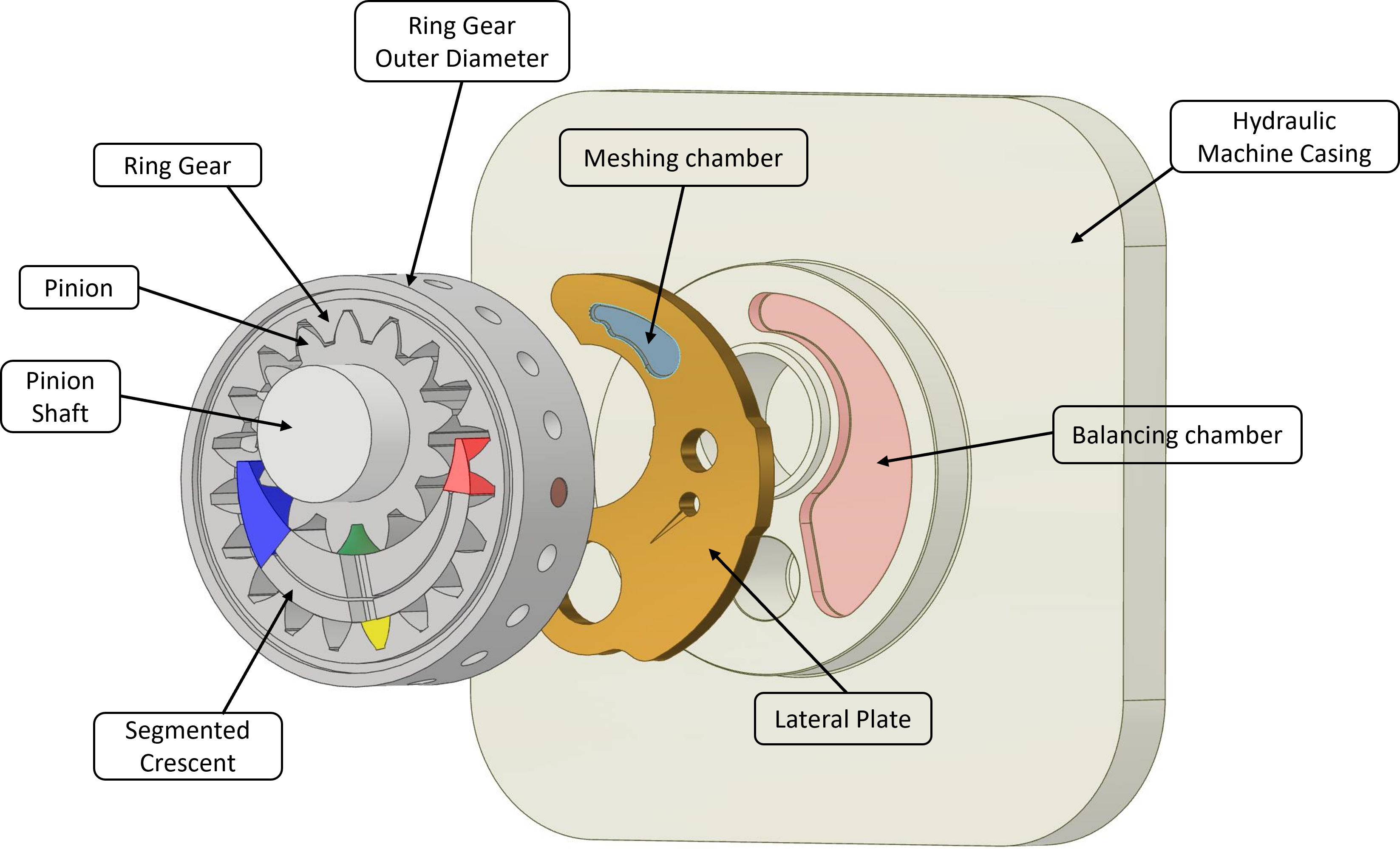
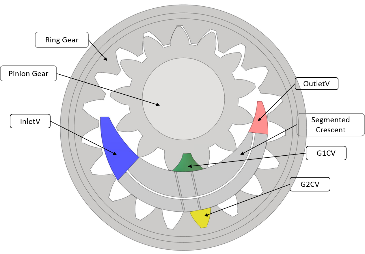
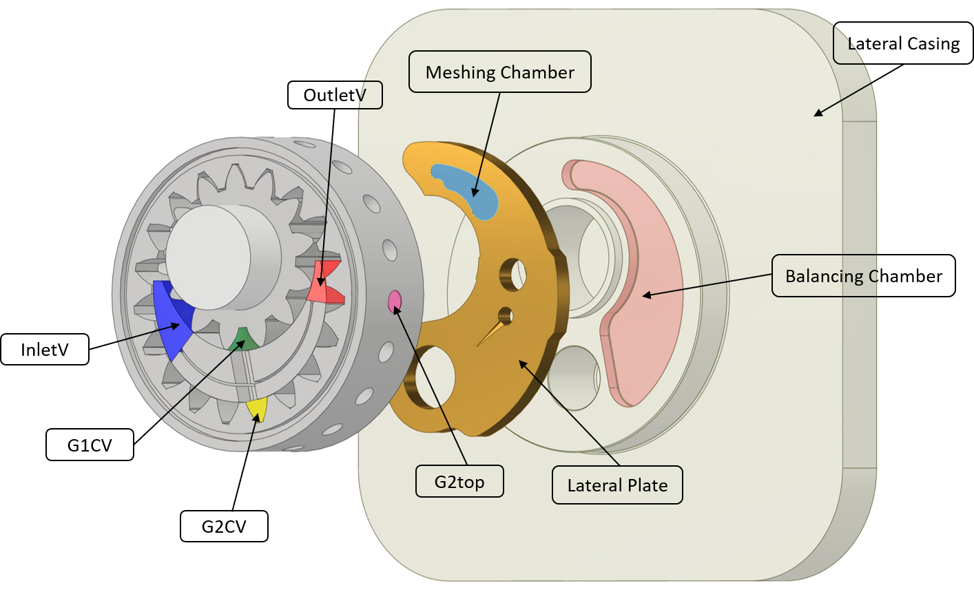
Before further exploring the Internal Gear Machine’s modeling approach, the terminology that will be used in this tutorial must be defined. The image below labels the main parts of internal gear machines. Internal gear machines comprise one external gear, referred to as a pinion meshing with an internal gear, referred to as ring gear. The most common design of IGM consists of a pinion supported on each side by a shaft and a journal bearing. The ring gear is supported by a journal bearing system defined by the gear’s outer diameter and the IGM housing. IGMs commonly use a radial compensation system consisting of a segmented crescent to isolate the high-pressure region from the low-pressure region. The two segments composing this part are designed with a sealing element between them. This arrangement allows for some fluid to go in between and, when pressurized, spread them apart pushing the inner segment against the pinion tooth tips, and the outer segment against the ring gear tooth tips, producing a perfect sealing effect without the need of imposing tight tolerances. Between the gear set and the hydraulic machine casing are mounted the lateral plates that constitute the axial compensation system. These components’ position is determined by the balance between the forces coming from the gear set side and from the balancing chamber side. The balancing chamber is a physical volume usually defined between the lateral plates and the hydraulic machine lateral casing and constrained by a sealing element.
IGM Modeling Concepts
Modeling Approach
Multics combines a lumped parameter approach with a 2D CFD approach to simulate IGMs. The best way to understand how Multics operates is to brake down its work in the sub-modules shown below. First, the gear profiles must be generated. Then, the gear profiles, together with the profile of the lateral connections must be input in the Geometrical Preprocessor. The function of the Geometrical Preprocessor is to provide all the geometrical data to the rest of the model. In summary, the Geometrical Preprocessor partitions the internal volume of the IGM in sub-volumes, and it calculates the connections between them and with the lateral openings. This connections are stored in a table as a function of the rotation angle and the position of the gears. The internal volumes and the connection areas are used in the Displacement Chamber solver to calculate the pressure in the internal sub-volumes, and the fluid exchanged between them. Once the pressure in the sub-volumes is calculated, the Dynamic Solver calculates the net force acting on the internal components of the IGM and determines their position. Based on the position of the bodies, the geometry of the IGM is updated. If the CFD sub-module is activated, the Reynolds equation can be solved to calculate the pressure distribution in the gaps. Integrating the pressure distribution, it is possible to precisely calculate the hydrodynamic force generated in the gaps and acting on the internal parts. The additional hydrodynamic force is finally applied to the moving parts of the machine.
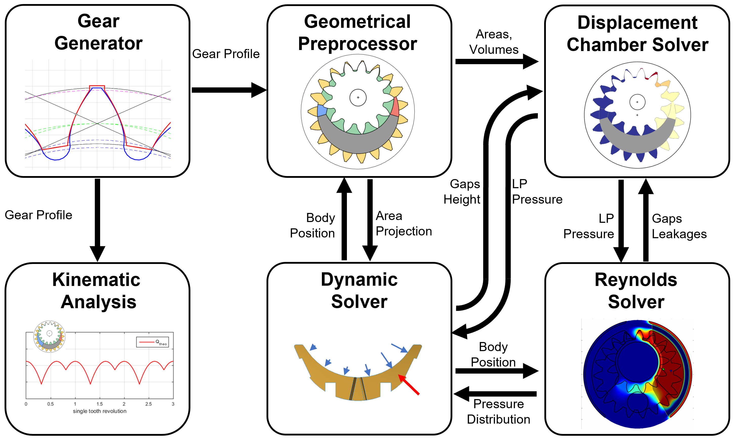
Geometrical Preprocessor, Displacement Chamber Solver, and Dynamic Solver are the core of the lumped parameter model and they are used to build the equivalent hydraulic circuit of the IGM.
Equivalent Hydraulic Circuit
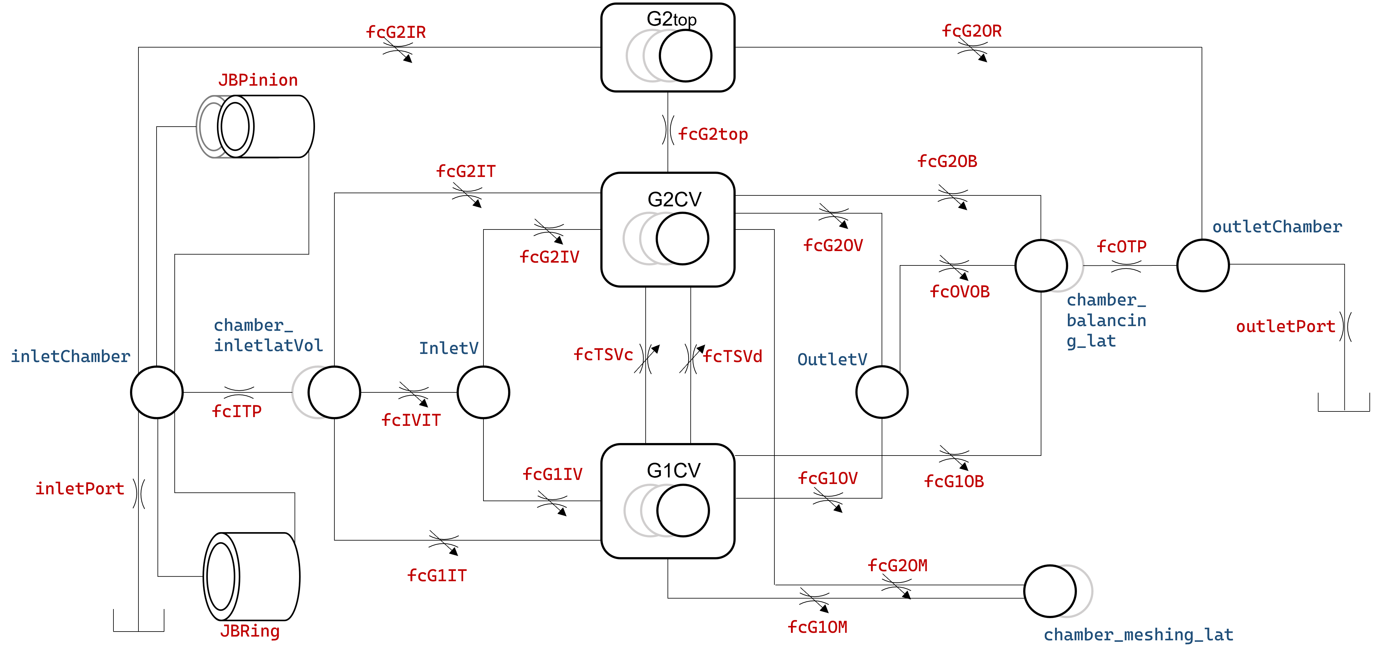
In the image above, the internal volumes of the IGM are reported as hydraulic chamber, and the connections between them as orifices. The images below clarifies what volume each chamber refers to, but for the sake of clarity, the path the working fluid follows will be discussed in this paragraph. The fluid is provided to the pump by a fluid source with infinite capacity and constant pressure named InletTank. The working fluid is sucked by the displacing action of the pump through the inlet port inletPort, and into the inlet chamber inletChamber. The typical shape for the inlet chamber is given in the figure below. In most cases the inlet chamber is the volume where the inlet fitting or flange is screwed in.
After the inlet volume, the fluid moves to a volume that is adjacent and in contact with the lateral surface of the gear set chamber_inletVol, which is shown in the figure below. The migration of the fluid between these two volumes happen through a connection fc_ITL which nature is highly depends on the morphology of the hydraulic machine. Generally this connection doesn’t resemble a standard orifice, and it is very wide, since it must ease the transition of the fluid feeding the hydraulic machine as much as possible. The inletChamber is also connected to the sides of each journal bearing of the hydraulic machine providing them fresh and low pressure fluid. The chamber_inletVol is the chamber that actually feeds the volumes internal to the gear sets, therefore, it presents a connection for each type of volume internal to the gear set.
The lateral volume on the side of the gear set chamber_inletVol feeds into the fluid domain defined between the two gears’ tooth profiles following the axial direction. Such fluid domain is often referred to as the gear space volume, which consists of the following types of volumes: G1CV and G2CV (often referred to as the tooth space volumes, or TSVs, which are volumes defined to each single gear tooth); and InletV and OutletV, which are variable volumes defined to complete the gear space volume domain. In common IGMs, InletV and OutletV are often found defined by the ring gear inner circle, the pinion gear addendum and the profile of the crescent. Figure below shows the shapes of these gear space volumes.
As per the fluid connection from the above mentioned the lateral volume chamber_inletVol, the chamber_inletVol connects to the volume InletV to feed in the fluid, and it chamber_inletVol connects to G1CV and G2CV, so that fluid enters the TSVs directly when the TSVs expand their volumes. The area of the connections between chamber_inletVol and the volumes internal to the gear set is decided based on the gear geometry, which also depends on the instantaneous gear rotation angle. The area and hydraulic diameter of these connections are of the prime interests in the process of setting up the fluid domain model for an IGM, and such calculations will be carried out by the Geometrical Preprocessor, a module that will be described in the next sections.
As indicated in hydraulic circuit of the hydraulic machine, the tooth space volumes of pinion and ring gear communicate with each other through the connection fcTSVc and fcTSVd. These are the connections that allow the exchange of working fluid when the tooth space volumes transition through the meshing zone.
Fluid displacing in an IGM is closely related to the fact that the tooth space volumes get their volumes downsized when the gear teeth on the two gears approach the meshing region. At such location, a variable volume OutletV communicates with the tooth space volumes through through the variable area connection fcG2OV and fcG1OV.
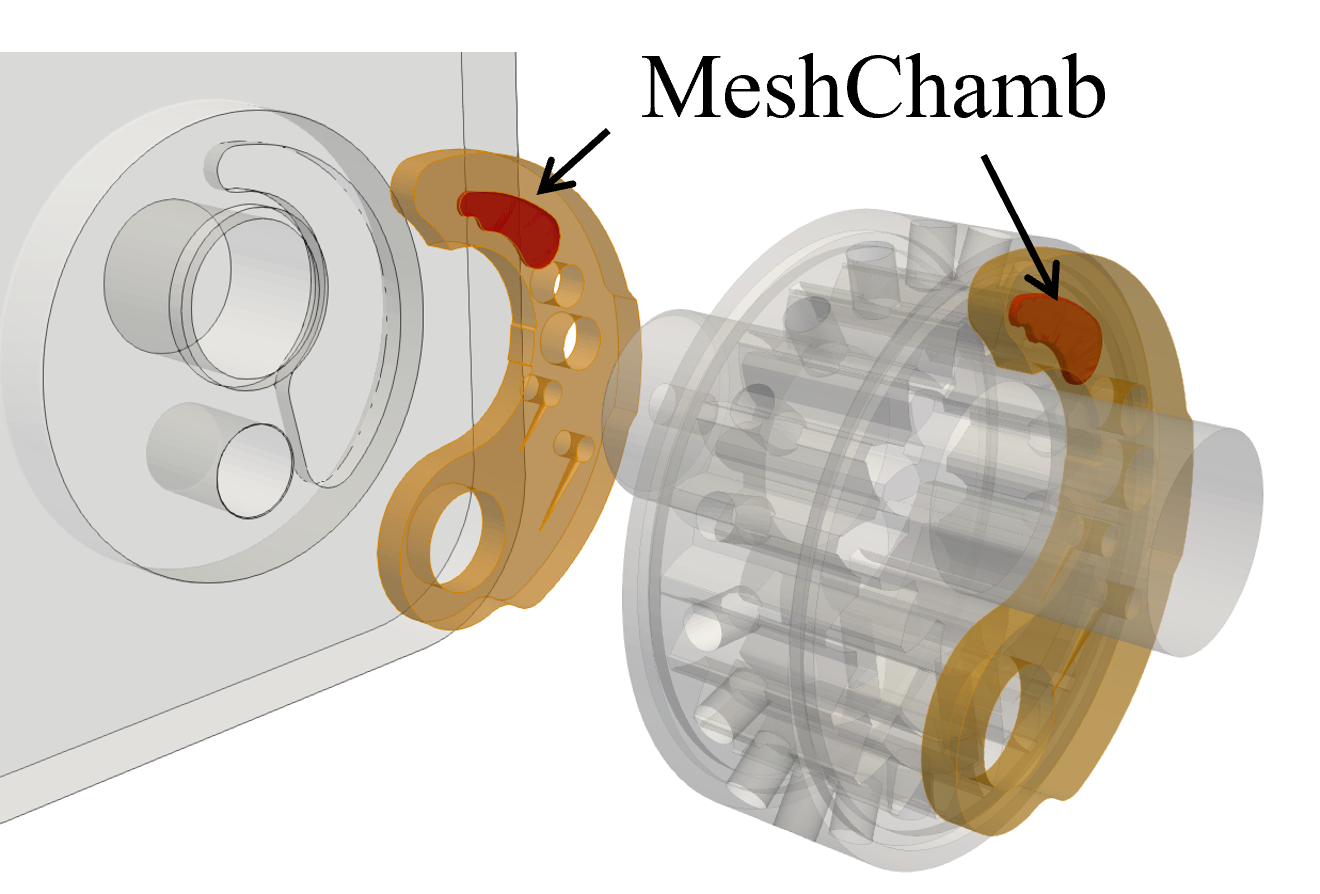
The tooth space volumes also communicate with the chamber_meshing_lat, which is a control volume defined by an axial recess facing the gear lateral surface, and located in proximity of the meshing chamber, as the figure below highlights.
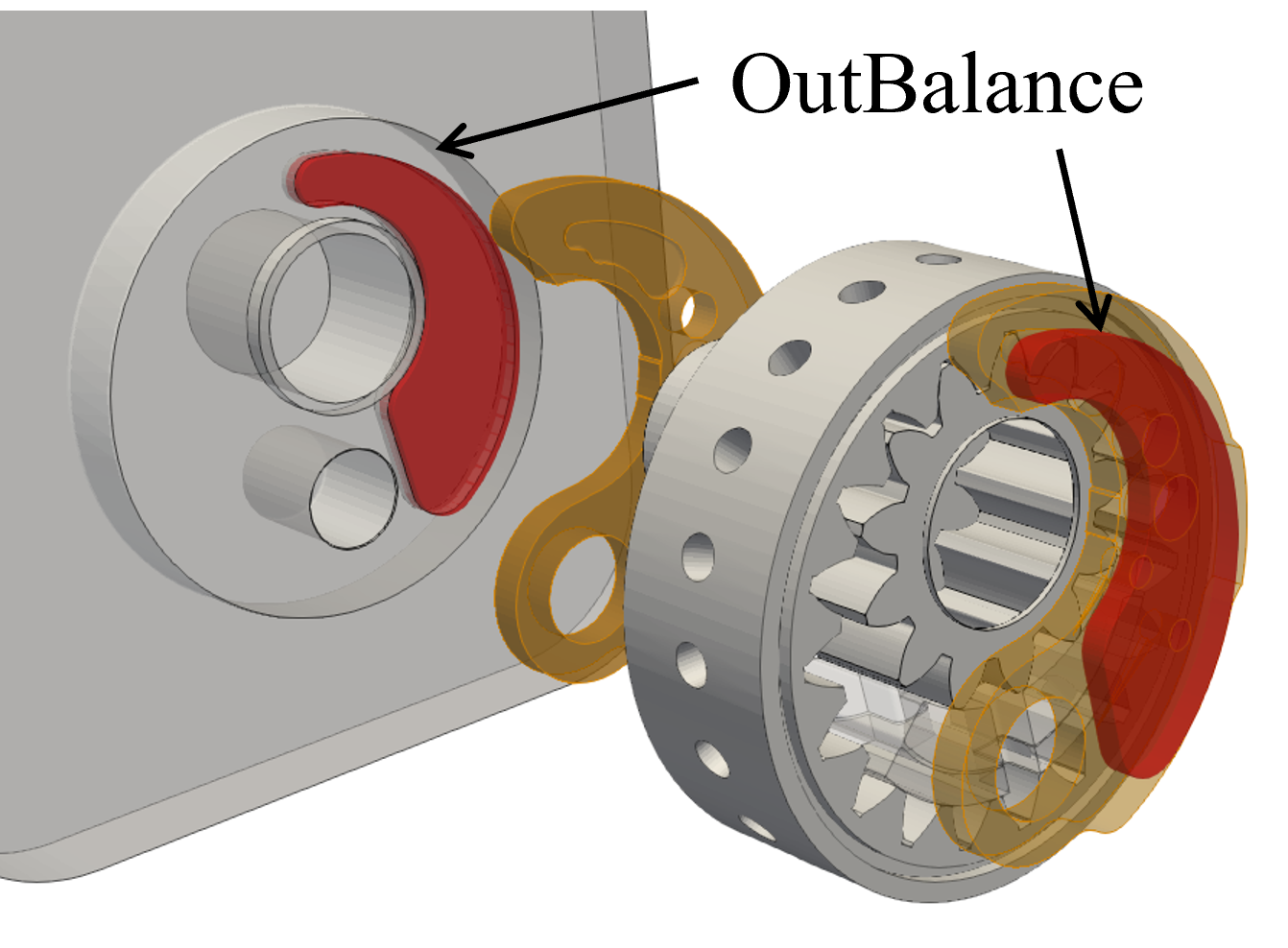
The tooth space volumes and OutletV also communicate with chamber_balancing_lat which is the chamber of high pressure fluid defined by a seal on the back of the thrust plates constituting the axial compensation system, which is shown in the figure below.
To displace, chamber_balancing_lat may be axially connected to the outletChamber through a connection fcOTP, if the IGM is only discharge in the axial direction. After that, outletChamber communicates with the circuit connected to the outlet through an orifice representing the outlet port of the gear machine and named outletPort.
Meanwhile, it should also be noted that, the two orifices fcITP and fcOTP are not the only possible fluid passages that connect the internal volumes of the gear machines with the inlet and outlet volumes. As shown in the figure, the ring gear presents holes named G2top (highlighted in the figure below) and located between each tooth that puts in communication the ring gear tooth space volumes and its outer diameter. Depending on the angular position of the ring gear and the morphology of the case of the IGM, these holes can communicate with inletChamber, with outletChamber or simply with the lubricated interface of the ring gear journal bearing. When communicating with the inlet they may provide an additional mean for the fluid to fill the tooth space volumes; when connected to the outlet pressure they provide an additional passage for the displaced fluid, and they may reduce the peak of pressure generated in the meshing tooth space volumes; when connected the lubricated interface, they may diffuse high pressure flow and provide additional support to the ring gear. The holes G2top are modeled like small volumes inwardly connected with the ring gear tooth space volumes through the connection fcG2top and outwardly connected with the inlet and outlet chamber through fcG2IR and fcG2OR.
Once these files are generated, the template can be used to simulate an IGM. For more details on how the IGM is modeled, refer to this hydraulic schematic.
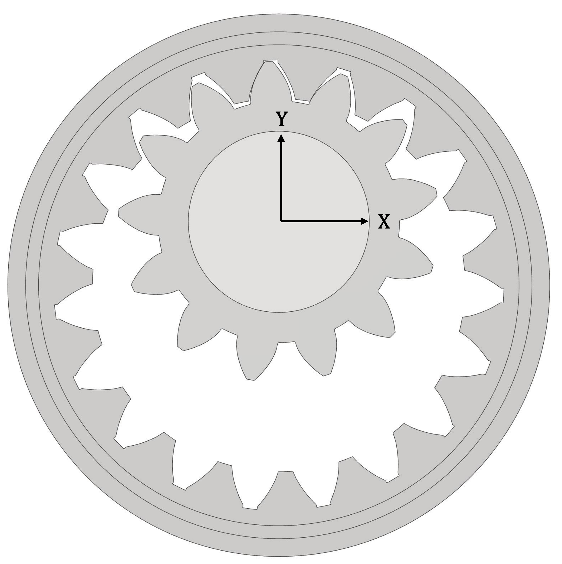
IGM Coordinate Systems
Lastly, the user may want to keep in mind that the whole model refers to the reference system shown in the image below.
Simulation Preprocessing Steps
Geometry Generation
To ensure proper results, the geometry of the IGM must be input in the simulation model. To input the geometry, the user is required to set geometrical dimensions, clearances, input the gear set profile, and other morphological information that can be easily extrapolated using the pre-processing tools provided with the simulation software. While the geometrical dimensions and clearances may be intuitive for a hydraulic machines designer and can be found in the engineering drawings or 3D model, the generation of the gears profile and the other features can be more challenging, and for this reason is described in a dedicated section.
Gear Generator
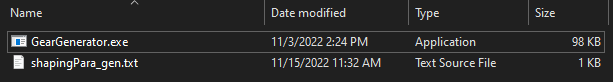
The Gear Generator is a software generated in-house and provided in the form of an .EXE file that generates the gears profile.
Together with the GearGenerator.exe file is provided a shapingPara_dim.txt file that must be placed in the same folder of the GearGenerator.exe file. shapingPara_dim.txt contains the geometrical inputs required to generate the gears profile using the geometrical definition of involute profile.
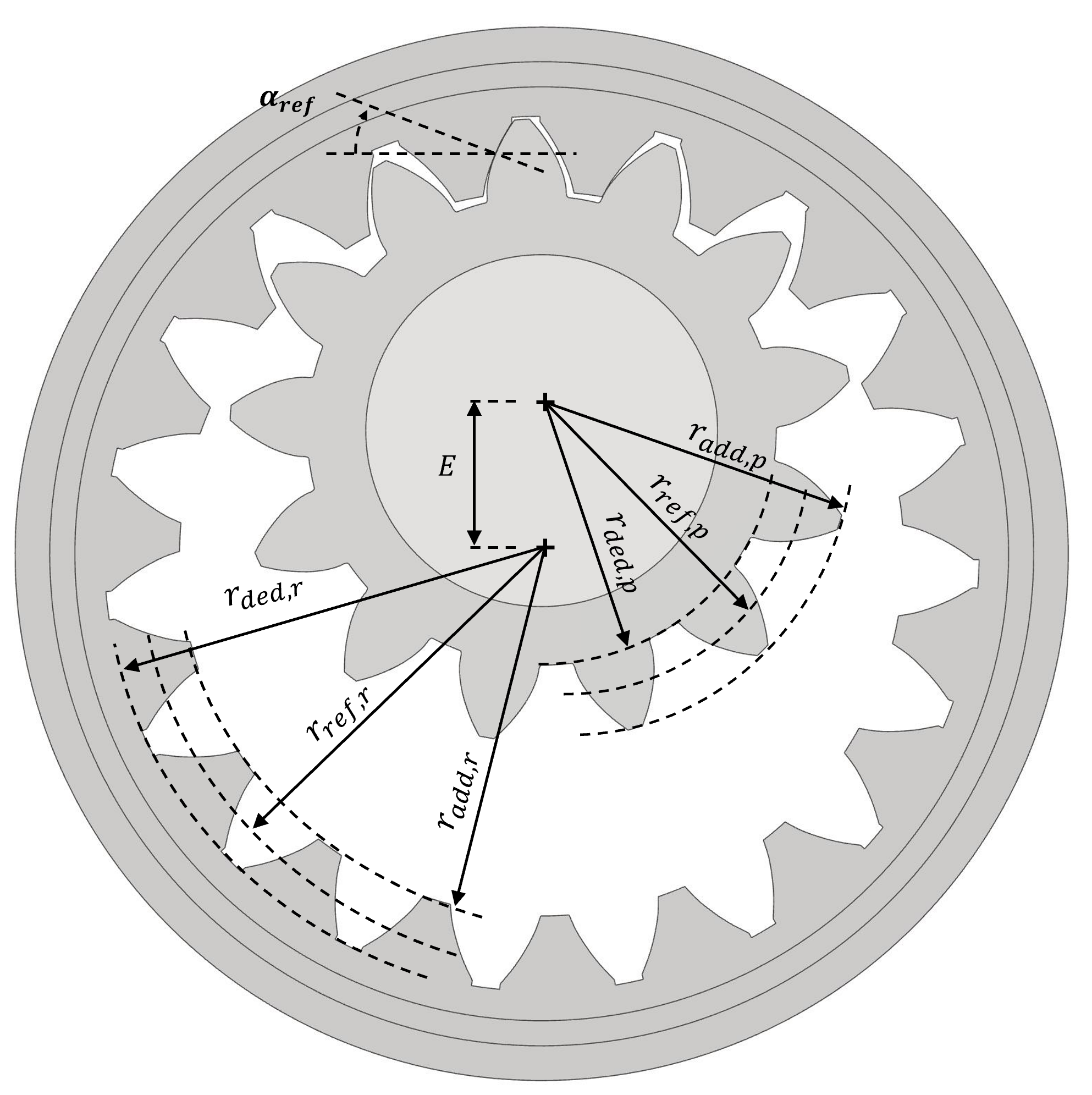
The inputs required to generate the gears profile are listed below, and highlighted in the figure right after.
N_teeth_pinion - Number of teeth for pinion gear [-]
r_ref_pinion - Pinion gear reference circle radius [mm]. Note r_ref_pinion*2/N_teeth_pinion gives pinion gear’s modulus.
alpha_ref_pinion - Pressure angle at reference circle radius location on pinion [rad].
r_minInvo_pinion - min circle radius where involute profile exists on the pinion gear [mm]
r_maxInvo_pinion - max circle radius where involute profile exists on the pinion gear [mm]
N_teeth_ring - Number of teeth for ring gear [-]
Nominal_gear_center_distance - gear center distance between pinion and ring gear at nominal position (when no load) [mm]
r_ref_ring - Ring gear reference circle radius [mm]. Note r_ref_ring*2/N_teeth_ring gives ring gear’s modulus.
r_minInvo_ring - min circle radius where involute profile exists on the ring gear [mm]
r_fillet - Fillet radius gear 1 root [mm]
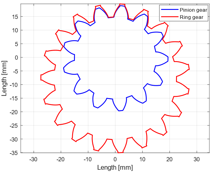
The output of this process are two .txt files containing the profile of the gears as a series of points. Opening each of the files it is possible to find the coordinates of the points organized in two columns, the first one representing the X coordinates and the second one representing the Y coordinates. The successful profile generation can be verified plotting the two profiles as shown in the image below.
Geometrical Preprocessor
After the generation of the gears profile, the user must use the Geometrical Preprocessor to automatically extrapolate crucial features of the IGM for the simulation tool. The extrapolation process consists in the partition of the internal volume of the IGM in many sub-volumes,the calculation of the area connecting the sub-volumes, and many other features value that are then stored in a table, named Geometry Table, as a function of the rotation angle of the gears. The Geometry Table is stored in a .txt with the name GeometryTable.txt.
Geometric Preprocessor Inputs
Additionally, the Geometrical Preprocessor embeds an option that allow the user to print the profiles of the internal volumes projection in the axial direction to set up the simulation of the axial compensation system.
To run the Geometrical Preprocessor, the user must place in the same folder the GeometryCode.exe file and the Inputs.txt file. The file Inputs.txt is the main input file, and operates as a glossary that lists all the input files required by the geometry preprocessor.
To successfully operate the GeometryCode.exe, the proper set up of the input file is necessary.
In this file, the following inputs can be found.
- Geometry table name:
Specify the name of the geometry table.
- Print activate:
The user can set this value to
0or1to print the profiles of the internal volumes projection in the axial direction.- Print format:
The user can set this to
.txtor.vtkto set the format of the profiles of the internal volumes projection in the axial direction. Printing these features as.txtfiles ease the conversion inPolygons Filesthat can be used in the simulation tool. Printing these features as.vtkease the visualization of the profiles using Paraview.- Input folder:
Path to the folder where the inputs for the Geometrical Preprocessor are stored. (Not working yet.)
- Output folder:
Absolute or relative path to the folder where the outputs of the Geometrical Preprocessor are saved.
- Gear profile path:
Absolute or relative path to the
.txtfile of the profile of the ring gear in a format compatible with what described in the previous section.- Pinion profile path:
Absolute or relative path to the
.txtfile of the profile of the pinion in a format compatible with what described in the previous section.- Gears parameter dictionary path:
Absolute or relative path to the file containing the Gear Parameters dictionary. For a detailed description of the inputs required in the Gear Parameters dictionary the user can refer to the dedicated section.
- Radial recesses dictionary path:
Absolute or relative path to the file containing the Recess dictionary. For a detailed description of the inputs required in the Recess dictionary the user can refer to the dedicated section.
- Lateral features profile path:
List of absolute or relative path to the lateral features profile
.txtfiles. Note that the Geometrical Preprocessor reads all the file listed as long as they are not separated by any new line. The new line must be placed at the end of the list and before the lateral groove profile path.- Lateral grooves profile path:
List of absolute or relative path to the lateral features profile
.txtfiles. Note that the Geometrical Preprocessor reads all the file listed as long as they are not separated by any new line.
While the first few entries are self explanatory the last four inputs do require more attention. Therefore, below is proposed a subsection that explains how to properly fill the Gear Parameters Dictionary, Radial Recesses Dictionary, Lateral Feature files, and Lateral Groove files.
Below are the inputs contained in the Gear Parameters Dictionary.
N1:Number of teeth of the pinion
N2:Number of teeth of the gear
rG2_out:Outer most radius of the ring gear profile.
gear_thickness:Axial thickness of the gear set.
range_Xita:This value can be copied from the output of the gear generator.
range_Xita2:This value can be copied from the output of the gear generator.
r_ref_1:Pinion standard pitch radius. This is the radius of the circle on which the tooth thickness is equal to the tooth space volume.
alpha_ref_1:Involute pressure angle on the standard pitch radius of the pinion.
rb1:Base radius of the pinion.
E:Nominal center distance of the two gears.
rp1:Pinion operating pitch diameter.
fi1:This value can be copied from the output of the gear generator.
fi2:This value can be copied from the output of the gear generator.
rb2:Ring gear base radius.
alpha_p1:Involute pressure angle on the operating pitch radius of the pinion.
C1:Coordinates of the center of the pinion. This entry must be provided as two entries listed one below the other. The first entry is the X coordinate, the second entry is the Y coordinate.
C2:Coordinates of the center of the ring gear. This entry must be provided as two entries listed one below the other. The first entry is the X coordinate, the second entry is the Y coordinate.
ra1:Addendum radius of the pinion.
MoreCutRatio:Dimension of the ring gear undercut expressed as fraction of the distance between adjacent teeth of the ring gear. If the value is equal to 1, the ring gear undercut is set equal to the distance between two adjacent teeth.
rT2_small:Minimum radius of the involute of the ring gear.
rT2_big:Maximum radius of the involute of the ring gear.
rT1_small:Minimum radius of the involute of the ring gear.
rT1_big:Maximum radius of the involute of the ring gear.
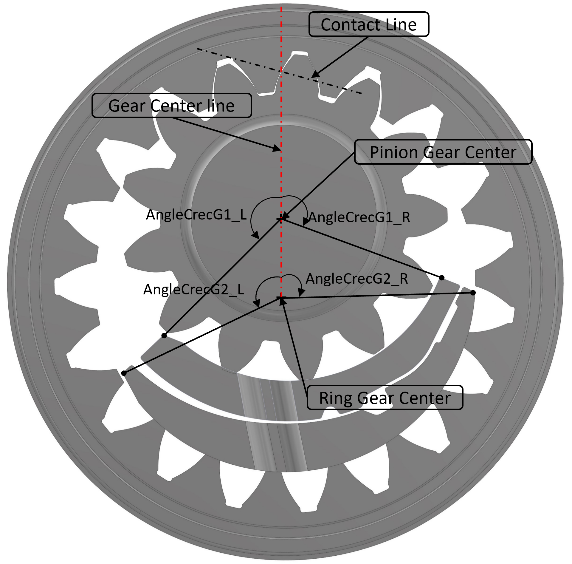
AngleCrecG1_L:Angle describing the position of the crescent left inner corner. The angle is the measurement between the vertical axis and the line connecting crescent inner corner and pinion gear center. CCW rotations must be reported as negative, while CW rotations must be reported as positive.
AngleCrecG1_R:Angle describing the position of the crescent right inner corner. The angle is the measurement between the vertical axis and the line connecting crescent inner corner and pinion gear center. CCW rotations must be reported as negative, while CW rotations must be reported as positive.
AngleCrecG2_L:Angle describing the position of the crescent left outer corner. The angle is the measurement between the vertical axis and the line connecting crescent outer left corner and ring gear center. CCW rotations must be reported as negative, while CW rotations must be reported as positive.
AngleCrecG2_R:Angle describing the position of the crescent right outer corner. The angle is the measurement between the vertical axis and the line connecting crescent outer right corner and ring gear center. CCW rotations must be reported as negative, while CW rotations must be reported as positive.
CrecG2_ratio:Not used.
ACrecG2_gapL:Not used.
ACrecG2_gapR:Not used.
Below is reported a figure showing the reference system used to identify the geometry of the crescent.
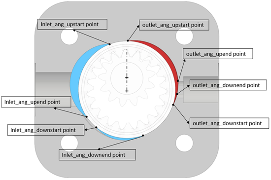
Some IGMs present holes that connect the ring gear TSVs to its outer diameter. During operation these holes face the IGM case or some recesses manufactured in the case depending on the rotation angle of the ring gear. The Geometrical Preprocessor can capture the opening area of these holes, but the user must input the geometrical characteristics of the recesses using the Radial Recess Dictionaries.
inlet_ang_upstart:The angle between the gear center line and the line from ring gear center to the inlet angle
upstartpoint (It is the point where inlet_up radial recesses start).inlet_ang_upend:The angle between the gear center line and the line from ring gear center to the inlet angle
upendpoint (It is the point where inlet_up radial recesses end).inlet_dR_up:Max depth of the Inlet up recesses.
inlet_ang_downstart:The angle between the gear center line and the line from ring gear center to the outlet angle
downstartpoint (It is the point where outlet_down radial recesses start).inlet_ang_downend:The angle between the gear center line and the line from ring gear center to the outlet angle
upstartpoint (It is the point where outlet_up radial recesses start).inlet_dR_down:Max depth of the Inlet down recesses.
outlet_ang_upstart:The angle between the gear center line and the line from ring gear center to the outlet angle
upstartpoint (It is the point where outlet_up radial recesses start).outlet_ang_upend:The angle between the gear center line and the line from ring gear center to the outlet angle
upendpoint (It is the point where outlet_up radial recesses end).outlet_dR_up:Max depth of the outlet up recesses.
outlet_ang_downstart:The angle between the gear center line and the line from ring gear center to the outlet angle
downstartpoint (It is the point where outlet_down radial recesses start).outlet_ang_downend:The angle between the gear center line and the line from ring gear center to the outlet angle
downendpoint (It is the point where outlet_down radial recesses end).outlet_dR_down:Max depth of the outlet down recesses.
R_G2_radial_hole:The radius of the Radial holes on the ring gear.
convention:The user may want to leave it as 1.5707963267948966
holes_each_TSV:Number of Radial holes per each TSV.
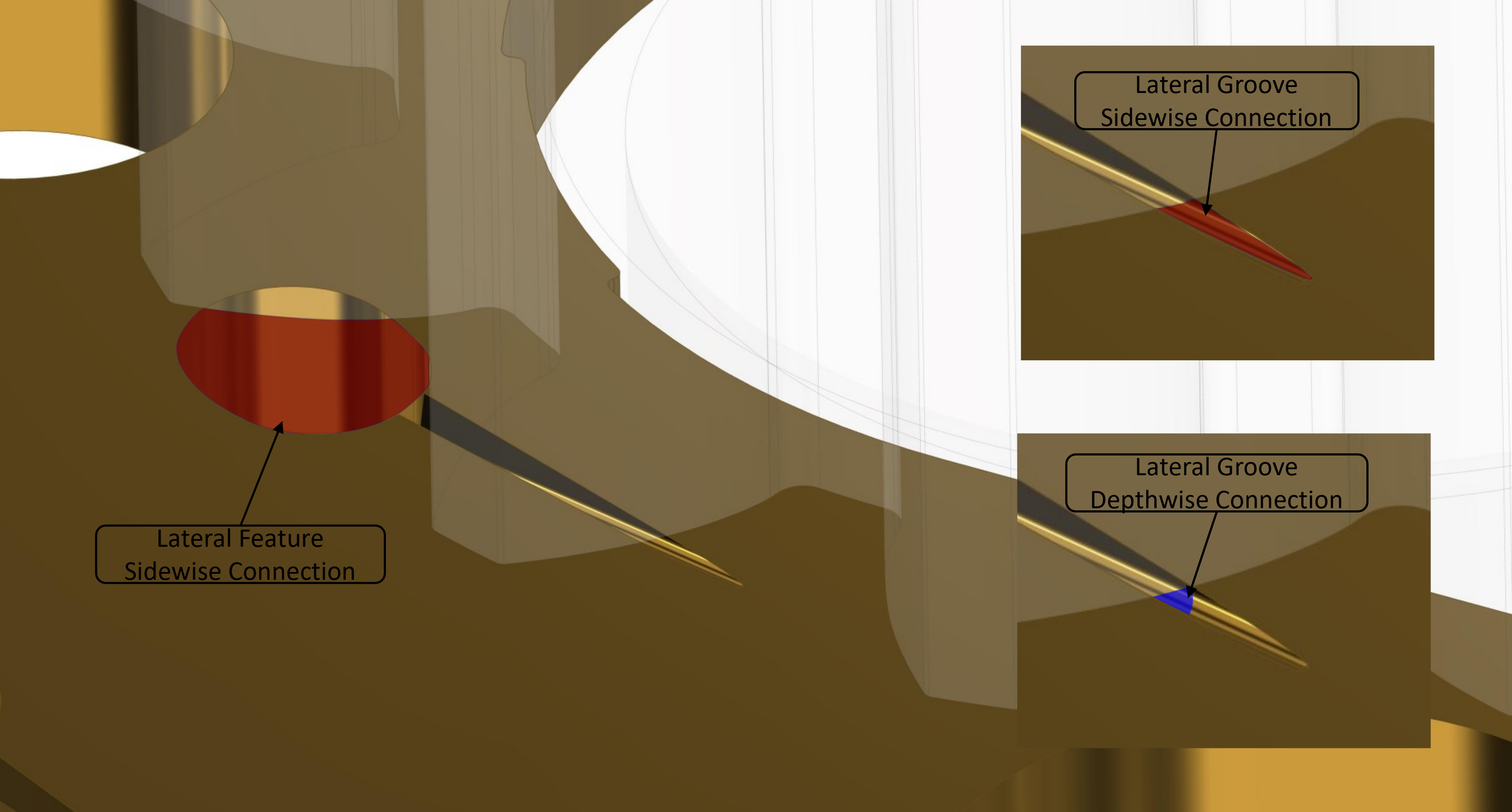
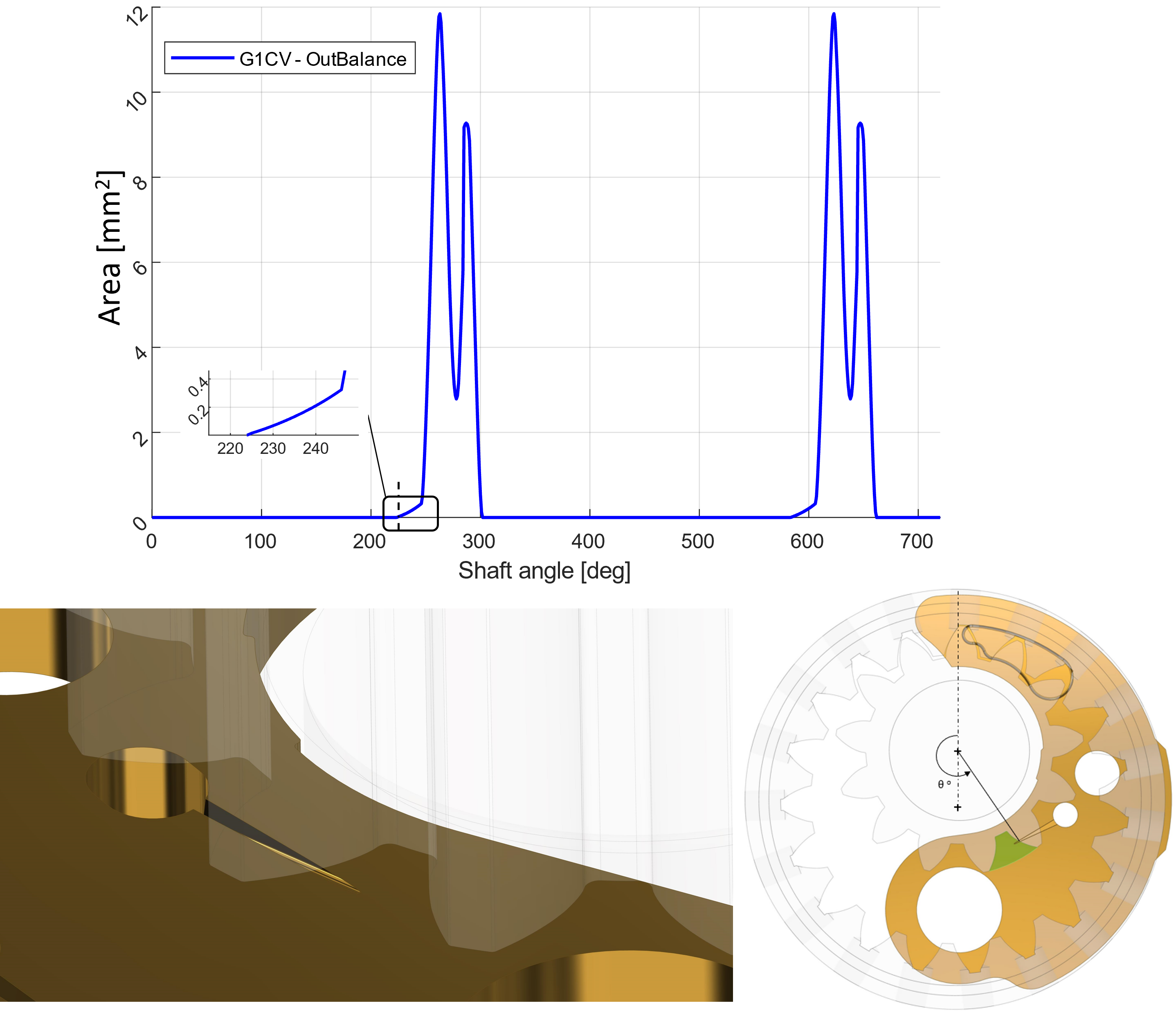
After filling the Gear Parameters Dictionary and Radial Recess Dictionary, the user must input the profiles of the Lateral Features and the Lateral Grooves. Both the Lateral Features and the Lateral Grooves are accounted as sidewise connection of the TSVs, and the main difference is how the connection area is calculated. In the model the Lateral Features are considered as opening with infinite depth. This means, that the connection area reported in the Geometry Table is always the area of the opening laying on the lateral surface of the gears. The Lateral Grooves instead, are openings with a finite depth, therefore, the Geometrical Preprocessor evaluates the minimum area between the sidewise connection area and the depth-wise connection area, and then saves in the Geometry Table the smaller of the two. The smaller area in fact determines the actual fluid constriction of the connection. In the image below the sidewise connection of a lateral feature is highlighted. For the groove instead, are highlighted both the side-wise (red) and depth-wise (blue) connection. For this specific case, the Geometrical Preprocessor uses the depth-wise connection since it is smaller.
The lateral features must be in a .txt format and must be represented like a series of points defining a closed contour. The file must be structured as shown in the picture below.
First, the user must specify what volume the connection connects the TSV with. The lateral features can connect the TSVs to the right or left balancing chamber, right or left meshing chamber, right or left drain chamber, the drain, or right or left port. To do so the user must use the following keywords: right_bala, left bala, right mesh, left mesh, drain, right port, left port.
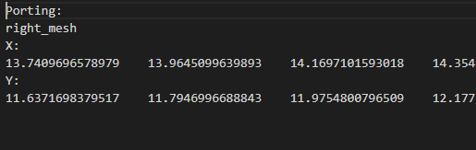
After that, the user must enter the X coordinates of the profile points under X:, and the Y coordinates of the profile points under Y:.
Then the user can input the Lateral Groove. To define a Lateral Groove, the user must fill a dictionary with the following information.
Porting:The user must specify what volumes the Lateral Groove connects the TSV to. As for the Lateral Feature, the user can use the following keywords:
right_bala,left_bala,right_mesh,left_mesh,drain,right_port,left_port- Reference gear:
The user must specify the gear center that the groove dimensions refer to. If the Lateral Groove parameters refer to the pinion the user can input
G1, if the parameters refer to the ring gear he/she can inputG2.- Groove type:
The user can specify whether the groove is straight or circular. To do so they can input
circularorstraight.- Groove cross section:
The user can specify whether the groove had a square or triangular cross section. To so the they can input
triangularorsquare.- Start point X:
X coordinate of the starting point of the groove. The starting point is the point with larger area.
- Start point Y:
Y coordinate of the starting point of the groove. The starting point is the point with larger area.
- End point X:
X coordinate of the ending point of the groove. The ending point is the point with smaller area.
- End point Y:
Y coordinate of the ending point of the groove. The ending point is the point with smaller area.
- Maximum width [mm]:
Width of the groove cross section at the starting point of the groove. In case the groove has a triangular cross section, this dimension defines the width of the base of the triangle.
- Maximum depth [mm]:
Depth of the groove cross section at the starting point of the groove. In case the groove has a triangular cross section, this dimension defines the height of the triangle.
- Minimum width [mm]:
Width of the groove cross section at the ending point of the groove. In case the groove has a triangular cross section, this dimension defines the width of the base of the triangle.
- Minimum depth [mm]:
Depth of the groove cross section at the ending point of the groove. In case the groove has a triangular cross section, this dimension defines the height of the triangle.
Geometrical Preprocessor Results Verification
The Geometry Table contains the value of many geometrical inputs required by Multics. Since the robustness and highly automation of the Geometrical Preprocessor, the user do not need to make any modification to the table or take any special precaution, however, they may be interested in verifying how some crucial values vary with the rotation angle. To do so, the user can plot these geometrical values directly from the Geometrical Table.
For example in the following image is represented the connection of the TSV with the balancing chamber through the holes machined in the plate. To realize a smooth pressurization, the TSV is gradually connected to the balancing chamber opening through a groove. The gradual connection between TSV and balancing chamber can be seen in the plot, before the sudden increase of area value.
Generation Of Data For Axial Compensation System Simulation
One of the features that multics offers is the simulation of the lubricated gap using a CFD approach to solve the Reynolds equation. While journal bearings often have a very simple cylindrical geometry, the lubricated gap located at the lateral surface of the gear set have a very complex geometry and multiple boundary conditions. To impose the boundary conditions, some files must be generated using the geometrical preprocessor.The files contains the pinion and ring gear TSV profiles as function of the rotation angle, the gear set profile, and all the profiles of the lateral features listed in the Lateral features profile path: of the Inputs.txt file.
To create the profiles the user must set the Print Activate field to 1 in the Inputs.txt file. Then the .exe file outputs in at the following relative path .\Output\PrintCoarse a long list of .txt files. These files can be grouped in few categories depending on what they represents. For example, the files starting with ‘g1cv3_’ represents the profile of the pinion TSV at different gear set rotation angle, the files starting with ‘g2cv3_’ represents the profile of the pinion TSV at different gear set rotation, and so on.
Before using the profiles as boundary conditions, they must be transformed in polygons using the the MATLAB script IGM_createPoly.m.
To ensure the proper post process of the profile and generation of the polygons, the user must fill some inputs inside IGM_createPoly.m.
N1:Number of teeth of the pinion.
N2:Ring gear number of teeth.
Ecc_neutral:Nominal distance between the axis of the gears.
R_pinionTip:Addendum radius of the pinion. Distance between the center of the pinion and tip of the tooth.
R_ringTip:Addendum radius of the ring gear. Distance between the center of the gear and tip of the tooth.
R_pinion_rootfillet_inner:Pinion radius at which the tooth tip fillet circle center is located
R_pinion_rootfillet_outer:Pinion radius at which the tooth base fillet circle center is located
Ring_cirGrv_Rin:Inner radius of the circular groove machined in the lateral surface of the rim of the ring gear.
Ring_cirGrv_width:Width of the circular groove machined in the lateral surface of the rim of the ring gear.
Ring_latFilm_maxR:Maximum radius of the film of the ring gear.
AngleCrecG1_L:Angle describing the position of the crescent left inner corner. The angle is the measurement between the vertical axis and the line connecting crescent inner corner and pinion gear center. CCW rotations must be reported as negative, while CW rotations must be reported as positive.
AngleCrecG1_R:Angle describing the position of the crescent right inner corner. The angle is the measurement between the vertical axis and the line connecting crescent inner corner and pinion gear center. CCW rotations must be reported as negative, while CW rotations must be reported as positive.
AngleCrecG2_L:Angle describing the position of the crescent left outer corner. The angle is the measurement between the vertical axis and the line connecting crescent outer left corner and ring gear center. CCW rotations must be reported as negative, while CW rotations must be reported as positive.
AngleCrecG2_R:Angle describing the position of the crescent right outer corner. The angle is the measurement between the vertical axis and the line connecting crescent outer right corner and ring gear center. CCW rotations must be reported as negative, while CW rotations must be reported as positive.
AngleCrecDuct:Angle describing the extension of the crescent compensation volume. The angle is the measurement between the vertical axis and the end of the groove. CCW rotations must be reported as negative, while CW rotations must be reported as positive.
R_CrecDuct:Radius of the crescent compensation volume.
width_CrecDuct:Radius of the crescent compensation volume.
portProf_index_min:Minimum index file of the port txt file. Look for the files in the following format (
portL_****.txt)portProf_index_max:Minimum index file of the port txt file. Look for the files in the following format (
portL_****.txt)tsvProf_index_min:Minimum index file of the pinion tooth space volume txt file. Look for the files in the following format (
g1cv3_****.txt)tsvProf_index_max:Maximum index file of the pinion tooth space volume txt file. Look for the files in the following format (
g1cv3_****.txt)RoutePort:Path relative the matlab file location that leads to the folder containing the port files.
Route:Path relative the matlab file location that leads to the folder containing the tooth space volume files.
RouteGear:Path relative the matlab file location that leads to the folder containing the gear profile files.
RoutLateralFeat:Path relative the matlab file location that leads to the folder containing the lateral feature profile files.
lateral_plate_prf_name:File name of the lateral plate profile file contained in the folder specified by
RoutLateralFeat.lateral_feature_name_set:Cell array containing in each cell the file name of one of the lateral features contained in the folder specified by
RoutLateralFeat.RouteWriteFile:Path relative the matlab file location that leads to the folder where the polygons can be printed.
IGM Simulation Inputs
After having generated a proper geometry table and lateral features, it is possible to proceed with the simulation of the hydraulic machine using Multics. To use Multics an input dictionary containing all the useful information for the simulation.
Required Files
To simulate the internal gear machine several files are needed.
resultsFile:Relative or absolute path to the file where the simulation results are printed. How to set up the simulation results file will be explained in a latter section.
geometryTableFile:Relative or absolute path to the file
GeometryTable.txt. This file is required for simulations using a lumped parameter and/or CFD approach. This file must be generated using the geometrical preprocessor following the information reported in the Geometrical Preprocessor section.g1cv_poly:Relative or absolute path of the polygon representing the pinion TSV projection in the axial direction. This is used in the lateral gap CFD-based simulation.
g2cv_poly:Relative or absolute path of the polygon representing the ring gear TSV projection in the axial direction. This is used in the lateral gap CFD-based simulation.
g1gear_poly:Relative or absolute path of the polygon representing the pinion gear profile. This is used in the lateral gap CFD-based simulation.
g2gear_poly:Relative or absolute path of the polygon representing the ring gear profile. This is used in the lateral gap CFD-based simulation.
left_poly:Relative or absolute path of the polygon representing the projection in the axial direction of the left variable volume. This is used in the lateral gap CFD-based simulation.
right_poly:Relative or absolute path of the polygon representing the projection in the axial direction of the right variable volume. This file is used in the lateral gap CFD-based simulation.
g1snapper_poly:Relative or absolute path of the polygon representing the pinion lateral lubricated interface snapper. This file is not required, but it improves the quality of visualization of the CFD results.
g2snapper_poly:Relative or absolute path of the polygon representing the ring gear lateral lubricated interface snapper. This file is not required, but it improves the quality of visualization of the CFD results.
crescFilm_duct_poly:Relative or absolute path of the polygon representing the activation chamber of the radial compensation system. This file is used in the lateral gap CFD-based simulation.
crescFilm_snapper_poly1:Relative or absolute path of the polygon representing the crescent inner segment lateral lubricated interface snapper. This file is not required, but it improves the quality of visualization of the CFD results.
crescFilm_snapper_poly2:Relative or absolute path of the polygon representing the crescent outer segment lateral lubricated interface snapper. This file is not required, but it improves the quality of visualization of the CFD results.
plate_poly:Relative or absolute path of the polygon representing the shape of the plate. This file is used in the lateral gap CFD-based simulation.
cirGrv_poly:Relative or absolute path of the polygon representing the circumferential groove machined on the lateral side of the ring gear or the plate. This file is used in the lateral gap CFD-based simulation.
meshingChamber_poly:Relative or absolute path of the polygon representing the meshing chamber machined on the plate. This file is used in the lateral gap CFD-based simulation.
POLY_radial_ring_HP_OutletGrooveUpper:Relative or absolute path of the polygon representing the recess machined in the hydraulic machine case and connected to the outlet. This file is used in the ring gear radial gap CFD-based simulation.
POLY_radial_ring_HP_OutletGrooveLower:Relative or absolute path of the polygon representing the recess machined in the hydraulic machine case and in between inlet and outlet port. This file is used in the ring gear radial gap CFD-based simulation.
POLY_radial_ring_LP_InletChamber:Relative or absolute path of the polygon representing the recess machined in the hydraulic machine case and connected to the inlet. This file is used in the ring gear radial gap CFD-based simulation.
POLY_radial_ring_HP_HoleNo1:Relative or absolute path of the polygon representing the holes radially machined in the ring gear TSV. This file is used in the ring gear radial gap CFD-based simulation.
fluidPropSub:Relative or absolute path of the file containing the table with the fluid properties of the working fluid below atmosphere pressure.
fluidPropSuper:Relative or absolute path of the file containing the table with the fluid properties of the working fluid above atmosphere pressure.
outputListFile:Relative or absolute path where the
outputList.htmlfile is printed by Multics. This file contains all the possible output values that can be listed to thesimulatoin_results.txtand printed during a simulation.vtkFilePath:Relative or absolute path where the
.vtkcontaining the CFD simulation results are printed.
Prime mover definition
In this section the prime mover is defined.
- PMtype:
This input allows the user to choose whether the prime mover is connected to the pinion or the ring gear. Set this to
1if the pinion is driving the hydraulic machine, or2if the ring gear is driving the hydraulic machine.- shaftSpeed0:
This input set the rotation velocity of the driving gear.
- rev2time:
Variable is set by default as
$2*PI/abs(shaftSpeed0)and should not be changed by the user. This can be used later in the input dict to obtain a time parameters as a function of number of prime mover revolution. E.g. to ensure that the simulation lasts exactly 2 revolutions the user can set the inputendPrintas$2*rev2time. Doing so, Multics automatically calculate the simulation time by which the prime mover gear will complete 2 revolutions and set it as simulation time limit.- deg2time:
Variable is set by default as
$PI/180/abs(shaftSpeed0)and should not be changed by the user. This can be used later in the input dict to obtain a time parameters as a function of prime mover rotation angle. E.g. to ensure that Multics starts printing the results after 90 degrees the user can set the inputstartPrintas$90*deg2time. Doing so, Multics automatically calculate the simulation time at which the prime mover accomplishes a rotation of 90 degrees and set it as start time to print the results.
Operating Conditions
- outletp:
Outlet pressure value.
- inletp:
Inlet pressure value.
- inletT:
Constant inlet tank temperature.
- outletT:
Constant outlet tank temperature.
- endPrint:
Simulation time at which the simulation ends.
- startPrint:
Simulation time at which the simulation starts to print the results in
simulation_results.txtfile.- startPrintCFD:
Simulation time at which the simulation starts to print the
.VTKfiles.- intvPrint:
Simulation time interval at which the simulation print the results.
- nSkipScreen:
Simulation time interval at which the simulation print the simulation progress to screen.
Fluid Properties
- fluidType:
This input can be set to 0, 1, or 2 depending on the modality of input the fluid property.
0 - Super atmospheric and sub atmospheric fluid properties with cavitation stored in ##-input fluid files.
1 - Super atmospheric fluid properties stored in input files, and sub atmospheric fluid properties are calculated with
cavType.2 - Fluid properties are expression based, and cavitation is calculated with one of
cavType.
- cavType:
This input can be set to 0 or 1.
0 - static cavitation
1 - dynamic cavitation
- nPtSub:
Number of points to evaluate at for sub-atmospheric pressure
- bunsenCoef:
Bunsen coefficient of the liquid.
- trappedAirVolFract:
Trapped air volume percentage.
- pVapH:
High vapor pressure.
- pVapL:
Low vapor pressure.
- gammaGas:
Released gas polytropic index.
- nuGas:
Gas kinematic viscosity.
- rhoGas:
Gas density at reference state.
- gammaVap:
Vapor polytropic index.
- nuVap:
Gas kinematic viscosity.
- rhoVap:
Gas density at reference state.
- jmK11:
Constant of the cavitation model proposed by Junjie, Vacca, and Casoli (https://doi.org/10.1016/j.simpat.2014.03.009). Only necessary if cavitation is enabled. DEFAULT: 4e-4
- jmK12:
Constant of the cavitation model proposed by Junjie, Vacca, and Casoli (https://doi.org/10.1016/j.simpat.2014.03.009). Only necessary if cavitation is enabled. DEFAULT: 0.2
- jmK21:
Constant of the cavitation model proposed by Junjie, Vacca, and Casoli (https://doi.org/10.1016/j.simpat.2014.03.009). Only necessary if cavitation is enabled. DEFAULT: 0.8
- jmK22:
Constant of the cavitation model proposed by Junjie, Vacca, and Casoli (https://doi.org/10.1016/j.simpat.2014.03.009). Only necessary if cavitation is enabled. DEFAULT: 0.2
- jmTau1500:
Reference time constant for 1500 rpm. DEFAULT: 0.04 s
- jmOmegaRef:
Reference angular velocity for scaling time constant. DEFAULT: 1500 rpm.
Geometry Inputs
To properly simulate an IGM the user must input the proper parameters defining the geometry of the IGM.
Equivalent Hydraulic Circuit Parameters
Before seeing in detail the values that the user must input, shown is below the image of the equivalent hydraulic circuit of the hydraulic machine reporting the volumes and connections of the model.
- inletVolume:
Volume where the fluid flows before entering the actual internal volume of the gear set. Usually, it can be assumed being the volume within the inlet fitting/flange of the hydraulic machine and all the volumes widely connected to it.
- outletVolume:
Volume where the fluid flows after exiting the actual internal volume of the gear set. Usually, it can be assumed being the volume within the outlet fitting/flange of the hydraulic machine and all the volumes widely connected to it.
- inletPortD:
Diameter of the port connecting the inletVolume and the inlet tank.
- outletPortD:
Diameter of the port connecting the outletVolume and the outlet tank.
- cqMax:
Maximum flow coefficient used in the orifice equation used to model the connection between the internal volumes of the hydraulic machine.
- cqMaxMesh:
Maximum flow coefficient used in the orifice equation used to model the connection between the meshing tooth space volumes of the hydraulic machine.
inletLateralVolume:Volume positioned between the gear set lateral surface and the hydraulic machine case on the low pressure side. This is the volume that supply the working fluid to the volumes internal the gear set.
balaChamberVol:Volume of the chambers located between the axial compensation system plates and the hydraulic machine case. This is the chamber of fluid that pressurizing activates the axial compensation system and pushes the plates toward the gear set lateral surface.
meshChamberVol:Volume of the chambers machined in the axial compensation system plate or hydraulic machine case in correspondence of the tooth space volumes meshing zone. This volume mitigates the pressure peaking that may generate in the meshing zone.
- HD_Orif_inletLat:
Hydraulic diameter of the port connecting
inletVolumechamber andinletLateralVolume.- Area_Orif_inletLat:
Area of the port connecting
inletVolumechamber andinletLateralVolume.- G2CV_RadialTunnel_Vol:
Volume of the cylindrical chambers
G2topmachined through the ring gear ring and connecting the tooth space volumes withinletVolumeoroutletVolume.rHoleOffset:Angular offset between the chamber
G2toplocated in the first ring gear TSV and the vertical axis. The vertical axis, also shown in the IGM Coordinate System section image, corresponds to the zero position.rHole:Radius of the discharge hole on the radial-external surface of the ring gear.
extRadG2:Radius of the radial-external surface of the ring gear.
plateThickness:Thickness of the plate in the axial direction.
Below is reported an image showing the parameters listed below.
angHpGrvStart:High-pressure recess starting angle.
angHpGrvEnd:High-pressure recess ending angle.
angLpGrvStart:Low-pressure recess starting angle.
angLpGrvEnd:Low-pressure recess ending angle.
axWidthHpGrv:High-pressure recess axial length.
axWidthLpGrv:Low-pressure recess axial length.
Gear Set Parameters
theorDisp:Theoretical displacement of the gear set.
estVolEff:Estimated volumetric efficiency. This value is used to calculate the initial value of the outlet orifice in case the outlet circuit connected to the outlet is the calibrated orifice one.
GearYoungsMod:Young’s modulus of the gears material.
GearPoisson:Poisson’s modulus of the gears material.
gearDensity:Density of the gears material.
gear1Mass:Mass of the pinion gear.
nTeethG1:Number of teeth of the pinion gear.
nTeethG2:Number of teeth of the ring gear.
naturalEcc:Distance of the gear centers when both of the gears are at neutral positions.
gammaMesh:Limiting shear strength proportionality constant (0.05 to 0.1 for hydraulic oils).
tipWidth:Tip Width for radial leakage.
toothWidth:Tooth Width for lateral leakage.
wholeDepth:Axial length of the gear set.
The user may refer to the image below to set the parameters defining the gear set tooth profile.
pinion_rOuter:Pinion gear’s gear outermost radius.
ring_rOuter:Ring gear’s gear profile’s outermost radius.
pinion_rRoot:Ring gear’s gear innermost radius.
ring_rInner:Ring gear’s gear profile’s innermost radius.
pinion_rAdd:Pinion gear’s gear addendum radius.
pinion_rDed:Pinion gear’s gear dedendum radius.
pinion_rRef:Pinion gear’s gear reference radius.
ring_rAdd:Ring gear’s gear addendum radius.
ring_rDed:Ring gear’s gear dedendum radius.
ring_rRef:Ring gear’s gear reference radius.
pinion_rBase:Pinion gear involute profile base radius.
ring_rBase:Ring gear involute profile base radius.
pinion_InitEcc_x:Pinion gear initial eccentricity in x direction.
pinion_InitEcc_y:Pinion gear initial eccentricity in y direction.
ring_InitEcc_x:Ring gear initial eccentricity in x direction.
ring_InitEcc_y:Ring gear initial eccentricity in y direction.
pinion_NominalGearCenter_x:Pinion gear center x coordinate when the gear is under neutral condition eccentricity.
pinion_NominalGearCenter_y:Pinion gear center y coordinate when the gear is under neutral condition eccentricity.
pinion_NominalGearCenter_z:Pinion gear center z coordinate when the gear is under neutral condition eccentricity.
ring_NominalGearCenter_x:Ring gear center x coordinate when the gear is under neutral condition eccentricity.
ring_NominalGearCenter_y:Ring gear center y coordinate when the gear is under neutral condition eccentricity.
ring_NominalGearCenter_z:Ring gear center z coordinate when the gear is under neutral condition eccentricity.
Axial Compensation System Plates Parameters
plateDenisty:Density of the plates material.
plateMass:Mass of each plate.
plateIxx:Plate moment of inertia with respect to the X axis.
plateIyy:Plate moment of inertia with respect to the Y axis.
plateIzz:Plate moment of inertia with respect to the Z axis.
plateIxy:Plate moment of inertia with respect to the rotation about the Z axis.
plateIxz:Plate moment of inertia with respect to the rotation about the Y axis.
plateIyz:Plate moment of inertia with respect to the rotation about the X axis.
plateXc:X coordinate of the plate center of mass.
plateYc:Y coordinate of the plate center of mass.
plateLinerRigidness:Linear rigidness of the lateral plate.
plateClearanceMax:Maximum gap between plate and gear set lateral surface.
BalancingChambArea:Area projection in the axial direction of the chambers located between the axial compensation system plates and the hydraulic machine case. This is the chamber of fluid that pressurizing activates the axial compensation system and pushes the plates toward the gear set lateral surface.
BalancingChambCx:X coordinate of the area projection in the axial direction of the chambers located between the axial compensation system plates and the hydraulic machine case.
BalancingChambCy:Y coordinate of the area projection in the axial direction of the chambers located between the axial compensation system plates and the hydraulic machine case.
MeshingChambArea:Area projection in the axial direction of the meshing chamber.
MeshingChambCx:X coordinate of the area projection in the axial direction of the meshing chamber.
MeshingChambCy:Y coordinate of the center of the area projection in the axial direction of the meshing chamber.
BalancingSealArea:Area defined by the seal on the back the thrust plates of the axial compensation system.
BalancingSealCx:X coordinate of the centroid of the area defined by the seal on the back the thrust plates of the axial compensation system.
BalancingSealCy:Y coordinate of the centroid of the area defined by the seal on the back the thrust plates of the axial compensation system.
radiusRingCirGroove:Radius of the circumferential groove machined in the lateral surface of the ring gear.
plate_rInner:Inner radius of the lateral plate.
plate_rOuter:Outer radius of the lateral plate.
Crescent Parameters
To ease the interpretation of the following geometrical parameters, below is reported a figure showing the reference system used to identify the geometry of the crescent.
- AngDeg_Crec_GrvTilt:
Angle of the recess machined in the crescent that mates with the crescent pin. This feature determines the direction in which the crescent segments translates. This angle is measured with respect to the vertical axis shown in the reference system shown in the image reported in the IGM Reference System Section. 0 at vertical- up direction. CW = positive.
- AngDeg_Crec_PinionLeft:
Angle defining the crescent inner edge facing the left port starting from vertical axis shown in the image reported in the IGM Reference System Section.
- AngDeg_Crec_PinionRight:
Angle defining the crescent inner edge facing the right port starting vertical axis shown in the image reported in the IGM Reference System Section.
- AngDeg_Crec_RingLeft:
Angle defining the crescent outer edge facing the left port starting from vertical axis shown in the image reported in the IGM Reference System Section.
- AngDeg_Crec_RingRight:
Angle defining the crescent outer edge facing the right port starting from vertical axis shown in the image reported in the IGM Reference System Section.
- RadialClearance_Cresc_Pinion:
Clearance between pinion tooth tips and crescent.
- RadialClearance_Cresc_Ring:
Clearance between ring gear tooth tips and crescent
Lubricated Interfaces Parameters
LatAxialClearance:Constant lateral gap assuming the plate/case perfectly parallel to the gear set lateral surface. This parameter is considered only if the relative option is activated.
pinionJBclearance:Pinion gear journal bearing nominal radial clearance.
ringJBclearance:Ring gear journal bearing nominal radial clearance.
pinionJBlengthOneside:Pinion journal bearing axial length on one side only.
pinionJBshaftRadius:Pinion journal bearing radius.
ringJBlengthWhole:Ring gear journal bearing length.
ringJBRadius:Ring gear journal bearing radial clearance.
Simulation Options
Multics allow the user to choose between different option that modify the equivalent hydraulic circuit or how the physics are modeled.
tipleak_type:This option allows the user to choose how to model the leakages between gear set tooth tips and crescent segments.
0 - no leakage
1 - with leakage
2 - constant gap
axialFeat:This option allows the user to choose between an equivalent hydraulic circuit with lateral ports and chambers on both sides or both sides.
0 - one side
1 - both sides
ringJbRadCompType:This parameter allows the user to model the ring gear with or without radial ports
G2topand the inlet and outlet recesses.0 - no features
1 - radial ports
2 - radial recess
3 - radial ports and recess
isPrintatOrig:Flag notifying if VTKs should be print at film origin.
isSnapPoints:Flag notifying if VTKs points should be snap to boundary polygons.
isGearMoving:Flag notifying that the gear is moving x-y.
isGearTilting:Flag notifying that the gearing is tilting.
isGearMeshPen:Flag notifying that the meshing penetration is to be solved for.
isGearMacroDef:Flag notifying that the gearing is bending
isPlateMoving:Flag notifying that the plate/bushing in moving axially
isPlateTilting:Flag notifying that the plate/bushing is tilting.
Lubricating Interface Model Selection
Multics allows the user to choose how to model the lubricated interfaces. More precisely, the user can choose the following options.
pinion_JB_type:With this parameter the user can choose how the pinion gear journal bearing is modeled.
-1 - fixed in the nominal position
0 - impedance
1 - Reynolds on one side
2 - Reynolds mirrored
ring_JB_type:With this parameter the user can choose how the ring gear journal bearing is modeled.
-1 - fixed in the nominal position
0 - impedance
1 - Reynolds
latPart_type:With this parameter the user can choose whether the gear set lateral surface faces the axial compensation system plates or the case.
0 - no plate
1 - plate
latgap_type:With this parameter the user can choose how to model the lateral lubricated gap.
0 - no lateral gap
1 - analytical lateral gap
2 - Reynolds lateral gap on one side
3 - Reynolds lateral gap mirrored
latBalance_type:With this parameter the user can choose whether the gear set lateral surface faces the axial compensation system plates or the case.
0 - no balance
1 - plate balance
isPlateDef:Flag notifying if the plate deformation must be calculated and with what model.
0 - No deformation
1 - micro-macro analytical deformation
2 - influence matrix deformation (not available yet)
isJBDef:Flag notifying if the journal bearing deformation must be calculated and with what model.
0 - No deformation
1 - micro-macro analytical deformation
2 - influence matrix deformation
isJBFilmMixed:Flag notifying that the journal bearing mixed lubrication is to be solved for.
isLatFilmMixed:Flag notifying that the lateral gap mixed lubrication is to be solved for.
Film Parameters
When modeling a lubricated interface with the Reynolds equation it is necessary to set up several parameters.
maxCFLLAT:Maximum CFL number for lateral reynolds films. This can be set to simultaneously control
maxCFLJBPinionandmaxCFLJBRing. If these two variables are not set, Multics automatically refers tomaxCFLLAT.maxCFLJBPinion:Maximum CFL number for pinion journal bearing films. DEFAULT:
maxCFLLAT.maxCFLJBRing:Maximum CFL number for ring journal Bearing films. DEFAULT:
maxCFLLAT.delHFact:Percent change in gap height over a single explicit step (Lateral film).
delHfilmLat:Percent change in gap height over a single explicit step (Lateral film).
delHfilmJBPinion:Percent change in gap height over a single explicit step (Pinion journal bearing film).
delHfilmJBRing:Percent change in gap height over a single explicit step (Ring journal bearing film).
delVFact:Percent change in gap velocity over a single explicit step.
delVfilmLat:Change in lateral gap velocity over a single explicit step.
delVfilmJBPinion:Change in pinion journal bearing gap velocity over a single explicit step.
delVfilmJBRing:Change in ring gear journal bearing gap velocity over a single explicit step.
nPtsMaxJB_Pinion:Number of points maximum for pinion journal Bearing gap.
nPtsMaxJB_Ring:Number of points maximum for ring journal Bearing gap.
nPtsMaxLat_pinion:Number of points maximum for pinion lateral reynolds film.
nPtsMaxLat_ring:Number of points maximum for ring lateral reynolds film.
cellAspJB_Pinion:Aspect ratio of cells for pinion journal bearing.
cellAspJB_Ring:Aspect ratio of cells for ring journal bearing.
Numerical Parameters and Relaxation
integratorType:Integrator used to solve the lumped parameter system of equation. The user can choose between the following options:
0 - GSL BDF implementation
1 - LSODA integrator
2 - Runge Kutta
3 - Adams Bashforth/Moulton Predictor Corrector
filmSolverLat:Type of solver used to solve the lateral fluid film. The user can choose between the following options:
0 - Default for film type
1 - Explicit single step
2 - Explicit multi-step
-1 - Implicit single step
-2 - Implicit multi-step
filmSchemeJBPinion:Numerical scheme used to solve the Reynolds film that model the pinion journal bearing. The user can choose between the following options:
0 - Default for film type
1 - Explicit single step
2 - Explicit multi-step
-1 - Implicit single step
-2 - Implicit multi-step
filmSchemeJBRing:Numerical scheme used to solve the Reynolds film that model the ring gear journal bearing. The user can choose between the following options:
0 - Default for film type
1 - Explicit single step
2 - Explicit multi-step
-1 - Implicit single step
-2 - Implicit multi-step
ompNthreads:Number of threads to use (<=0 sticks to default).
maxSteps:Maximum steps for LSODA.
aTolConv:Absolute convergence tolerance Factor that multiplies constant characteristic value y_char,i.
rTolConv:Relative convergence tolerance based on current value.
writePrec:Decimal precision to print for each value in output files.
Simulation Results File
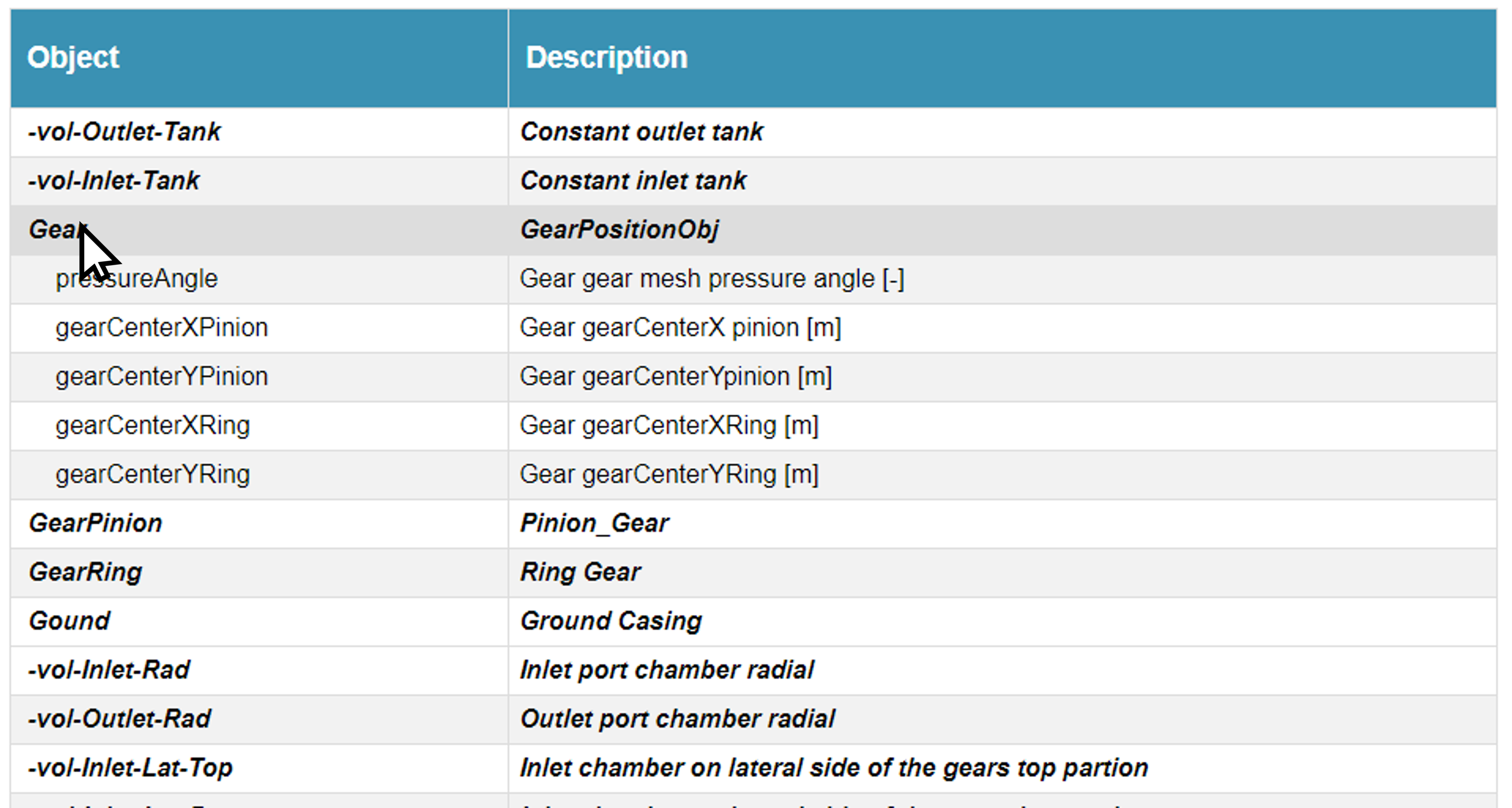
After setting up the inputDict.txt file, the user is ready to simulate double clicking the Multics.exe file. Every time the Multics.exe file is run it automatically generates the file outputlist.html. The file outputlist.html is customized according to the objects contained in the model, and it lists all the variables that is possible to output from the model. To access the variables belonging to an object, the user just need to click on the object name.
To actually print the variables, it is necessary to open the file simulation_results.txt and add the variables name within the printDict list. The name of the variable must start with an @ symbol. Moreover, the name in the outputList.html and the name listed in the printDict must be exactly the same, therefore the user is recommended to copy and paste it.
There are still a few features that can help the user through their simulation activities.
Firstly, the variables unit can be adjusted. For example, if a variable expresses a measure of length, such variable can be printed in meter [m], millimeter [mm], or microns [microns]. If a variable expresses a measure of angle, that variable can be print in degrees [deg] or radians [-].
Secondly, changing the settings of the simulation may add or remove objects from the simulation. A simple example is when the user switches from one journal bearing model and the other. Modifying the objects modeled by Multics also change the variable that can be printed. To account for this, the user may use a question mark ? before the name variable in the place of the @ symbol. Doing so, Multics will print the variable preceded by the question mark, only if it is present in the list of variables that can be printed. If the user misses to do so, listing in the printDict list a variable belonging to an object not included in the model will interrupt the simulation.
Finally, the user may find useful to add comments inside the printDict using the symbol #.
printDict{

        #       Comment
        @variable1 [unit1]
        @variable2 [unit2]

        ...
        @variableN [unit3]
        ..
        @pressureAngle [deg]
        @gearCenterXPinion [micron]

        ?variable4 [unit4]

}
Analyzing Results
Plotting Results
In the previous section the user learned how to output the values of the variables used in the model. In this section instead, it is illustrated how to interpret some of the most important results. This not only allows the user to make sure that the simulation is properly set, but also to gain fundamental insights regarding the simulation problem. Firstly, results regarding the lumped parameter model are shown and analyzed. Then, some results obtained enabling the CFD functionalities of the model are presented.
Lumped Parameter Model Results Analysis
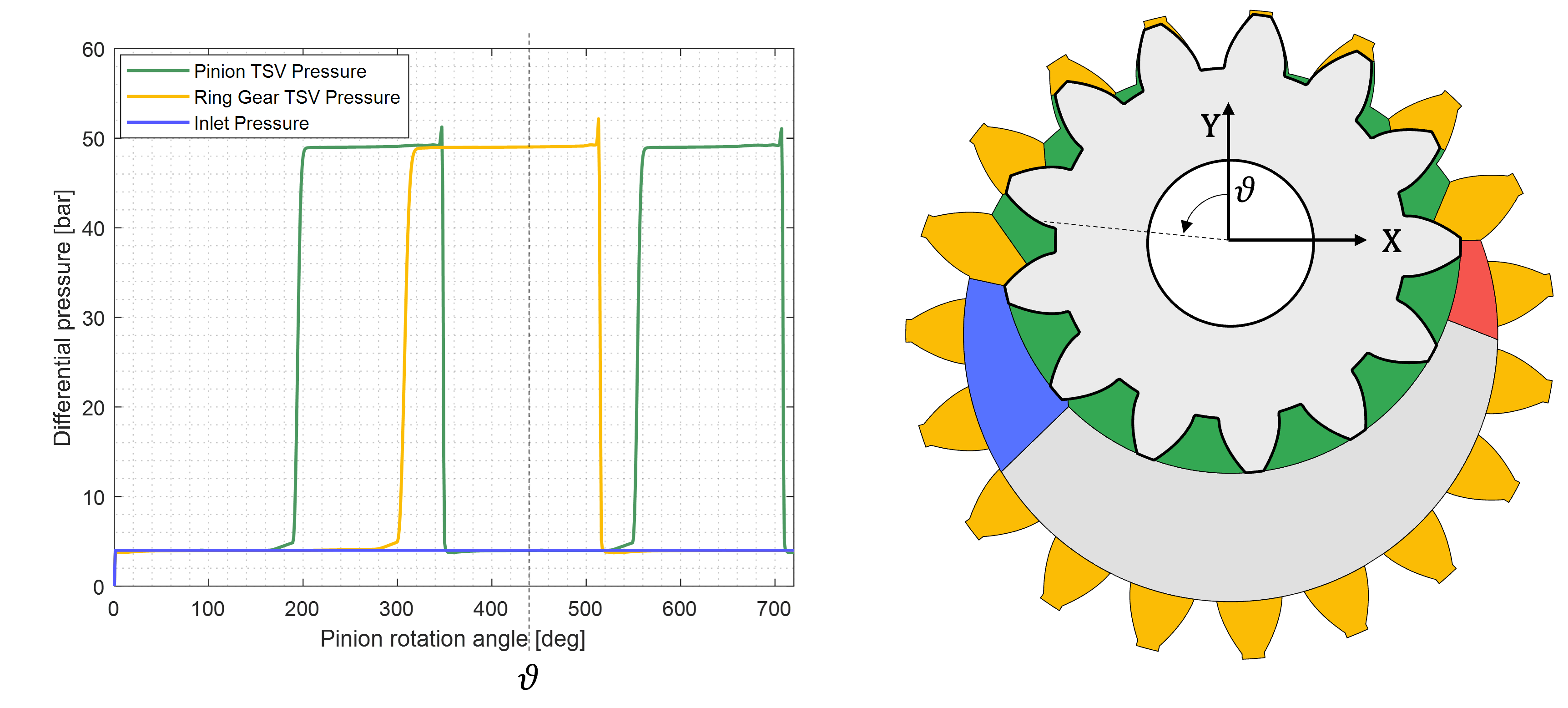
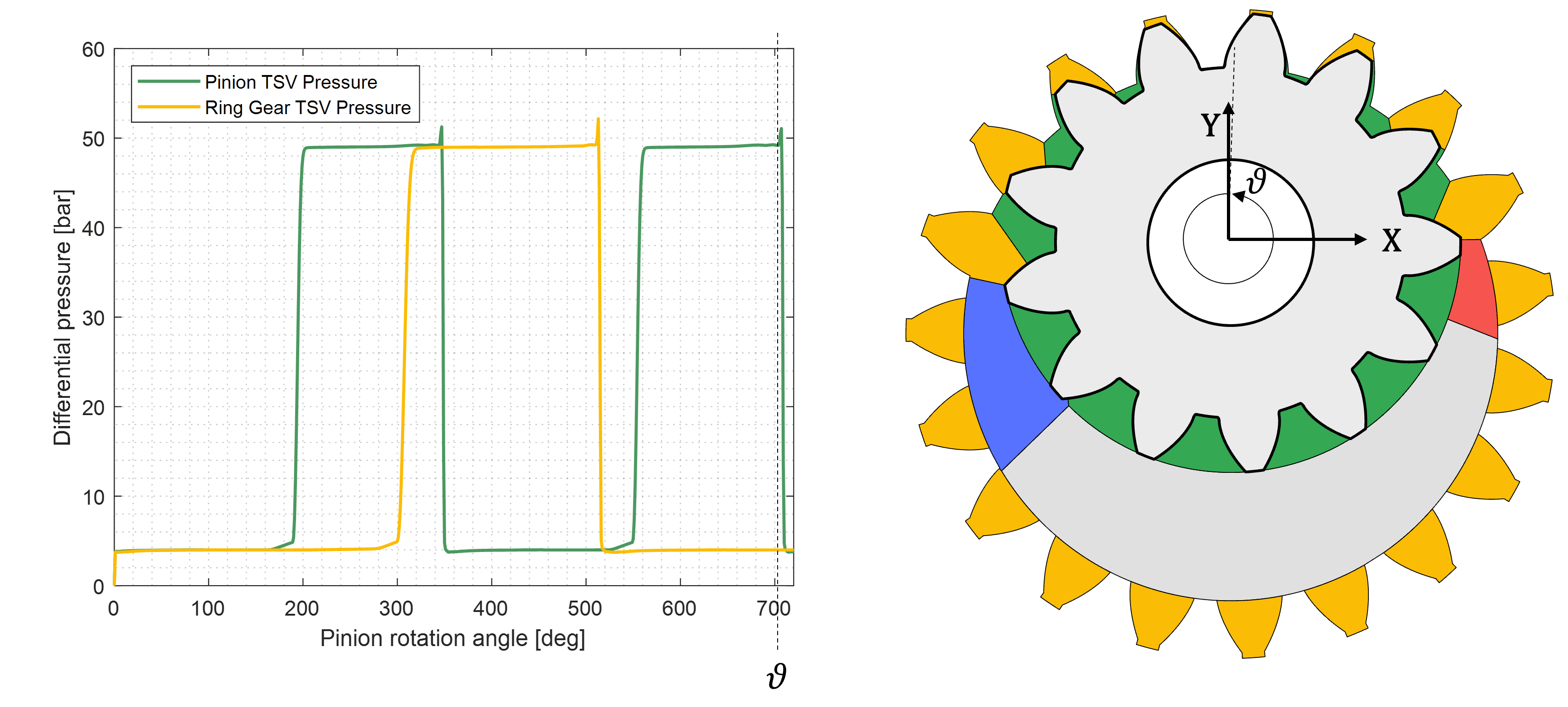
Tooth Space Volume Pressure profile
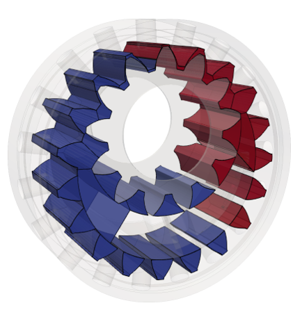
A very common variable that should be monitored by the user is the pressure build in the TSVs. In the figure below the pinion TSV are highlighted in green, and the ring gear TSVs are highlighted in yellow. From the image it is possible to see that, as expected by a steady state simulation, the pressure signals are periodical. Moreover, the pinion and ring gear TSV pressure profiles have a different period, that depends on the gear ratio of the gear set. The pinion TSV pressure signal, has a smaller periodicity due to the lower number of teeth. On the other hand the ring gear TSV pressure signal has a longer periodicity.
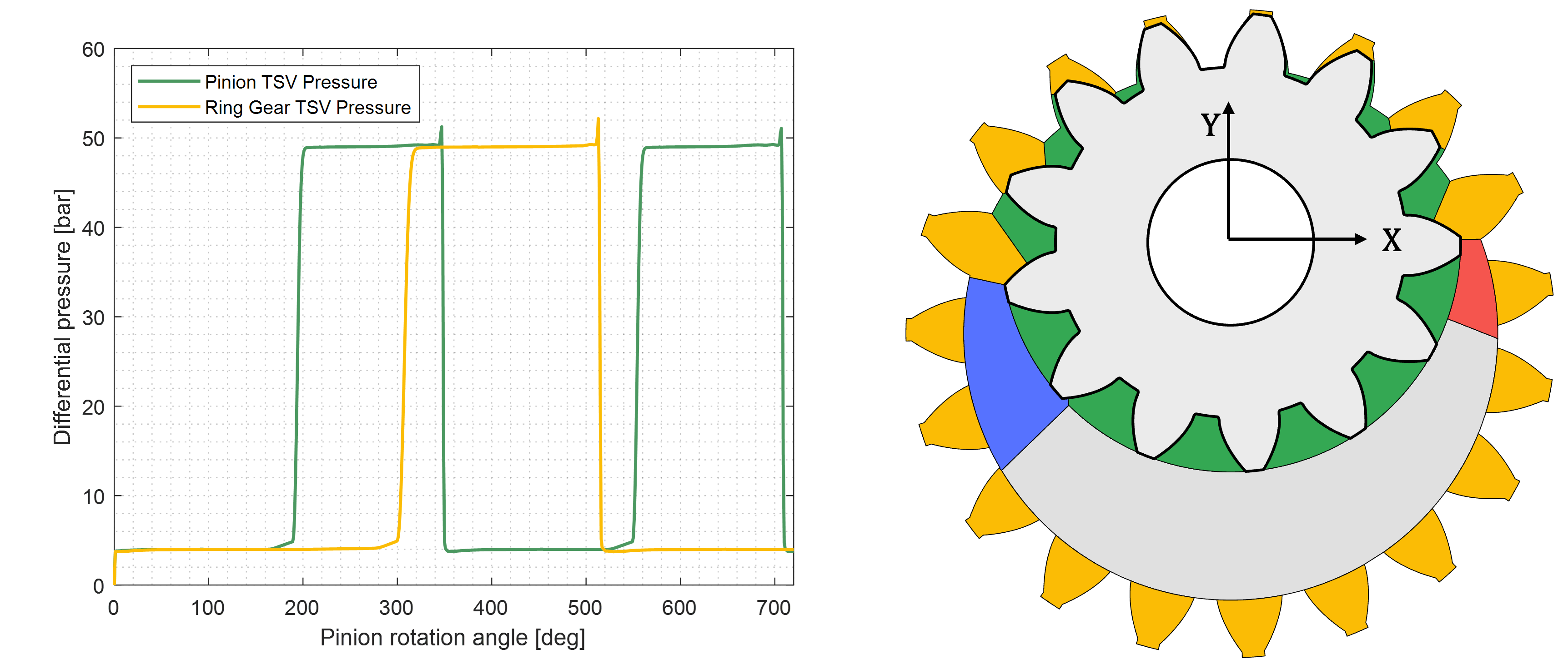
The pressure profile can give interesting information regarding the hydraulic machine that is begin simulated. Below are reported some consideration and interesting features for the pinion pressure profile. It must be noted that the user can extend the considerations presented below to the ring gear TSV pressure profile and gain equally important insights. To conduct the study, the TSV pressure profile can be divided in 5 phases which depends on the position of the TSV. Firstly, the TSV draws fluid from the low pressure port. As shown in the figure below the abrupt expansion of the TSV after the meshing zone produces a decrement of pressure in it. If the pressure of the fluid in the TSV goes below the saturation pressure, cavitation and incomplete filling may happen.
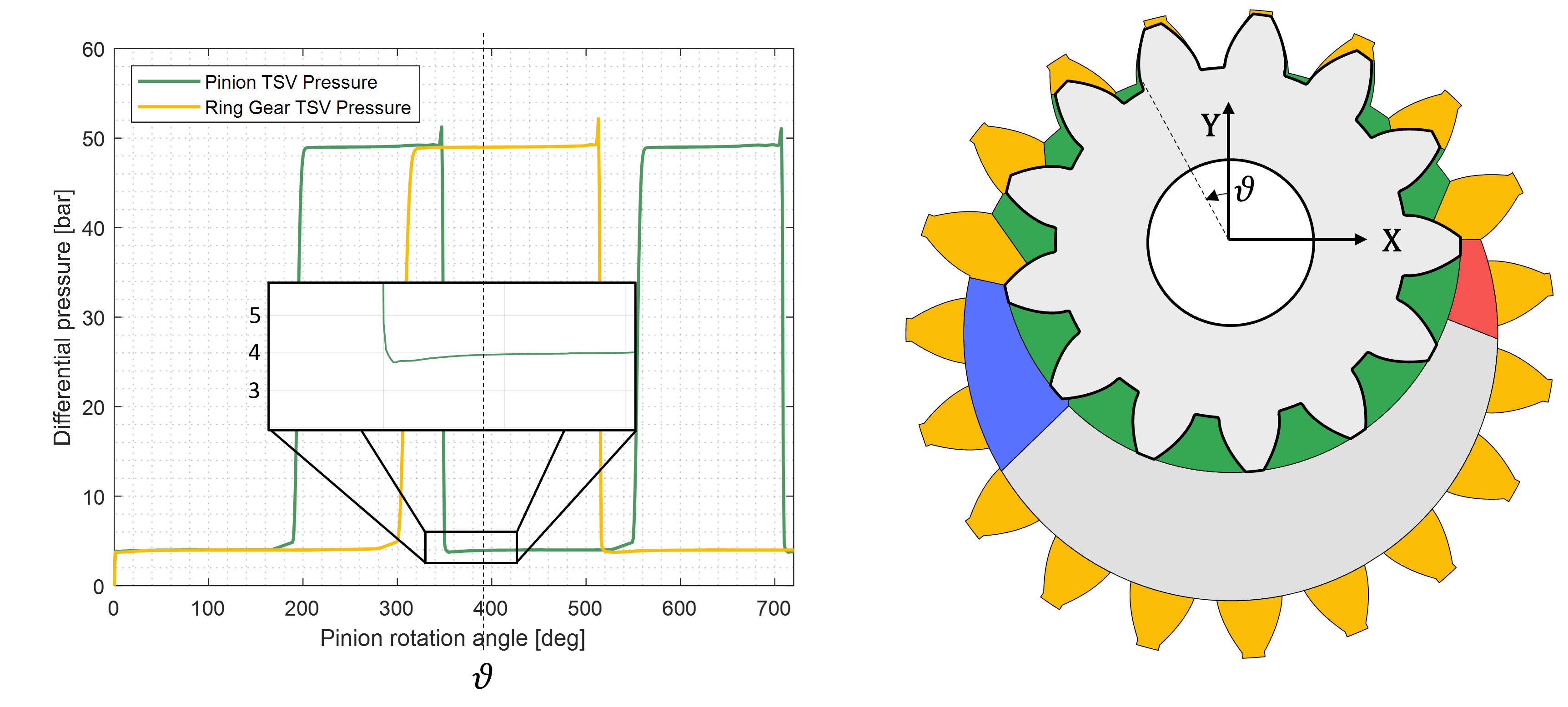
The second phase consists in the TSV being well connected to the LP volume of the hydraulic machine. Since the very effective connection between them, the TSV and the LP volume end up sharing the same pressure.
The third phase is characterized by the TSV transitioning undeformed between the pinion and crescent. During the process, the TSVs closer to the HP volume leak fluid in the analyzed TSV slowly increasing his pressure. The pressure slowly increases until the TSV connects with the high speed grooves, which consisting in a substantial connection with the HP volume, pressurize the volume almost instantaneously.

The fourth phase consists in the TSV being well connected to the HP volume of the hydraulic machine. Since the very effective connection between them, the TSV and the HP volume end up sharing the same pressure.

Finally, the TSV transition through the meshing zone where the TSV is at its minimum and the fluid is trapped inside it. This conditions generate a peak of pressure that must be limited properly sizing the timing of the ports. When the peak of pressure is too pronounced, it may lead to high noise and damage the hydraulic machine. On the other hand, if the TSV is too well connected with the inlet and outlet volume, cross-port flow may be established, leading to a substantial decrement of volumetric efficiency.
Gears Eccentricity
CFD Model Results Analysis
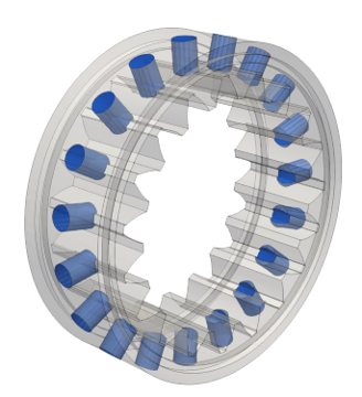
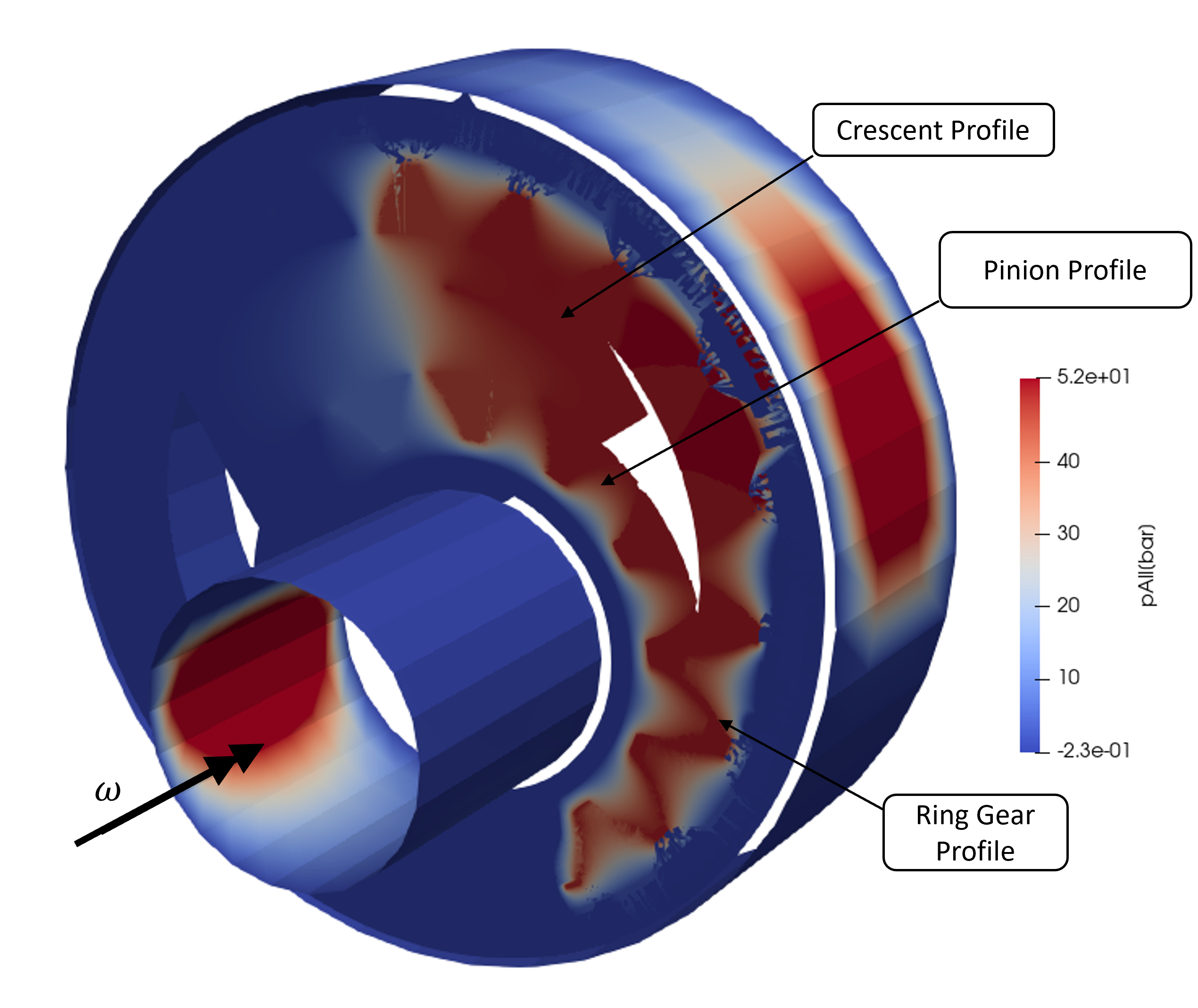
Multics allow the user to model the lubricated interfaces of the IGM. These interfaces are the pinion shaft journal bearing, the ring gear journal bearing, and the lateral gap, which is the gap between the gear set and the lateral plate. In the picture below, are reported these three interfaces where the pressure field is highlighted. The reader can recognize two cylindrical interfaces, the pinion and ring gear journal bearing respectively, and one flat circular interface which is the lateral interface.
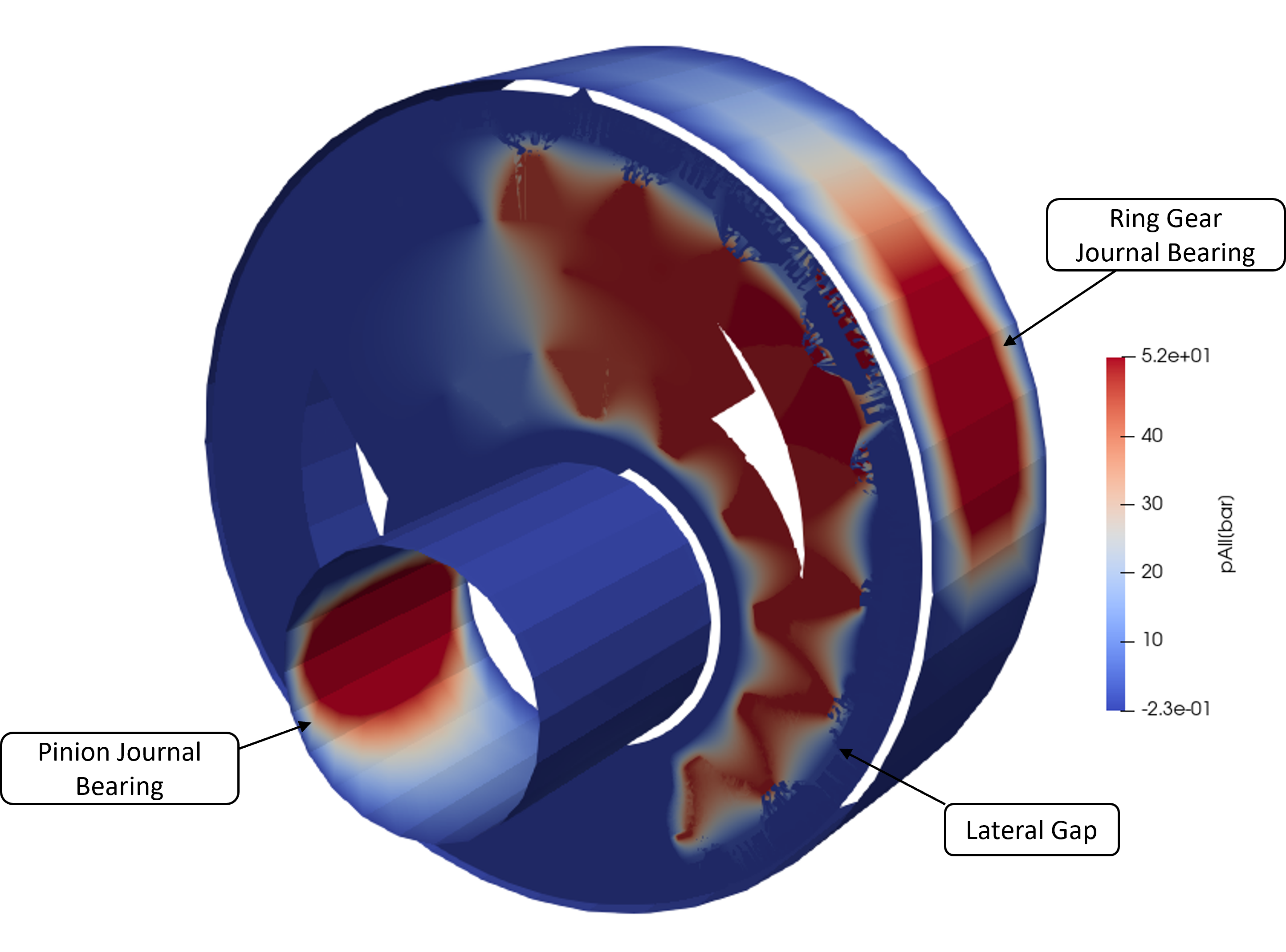
The pressure distribution can be analyzed to confirm whether or not the model is properly set up. Firstly, the lateral gap is analyzed. In the case reported in the image, the IGM is used as a pump and the gears rotate in the clockwise direction pressurizing the working fluid enclosed in the right-side of unit. As expected, the results show high pressure fluid in the right-side part of the IGM diffusing into the gap from the internal volume of the IGM. More precisely, the user can see the profile of the gear set and crescent highlighted by the gradient of pressure.
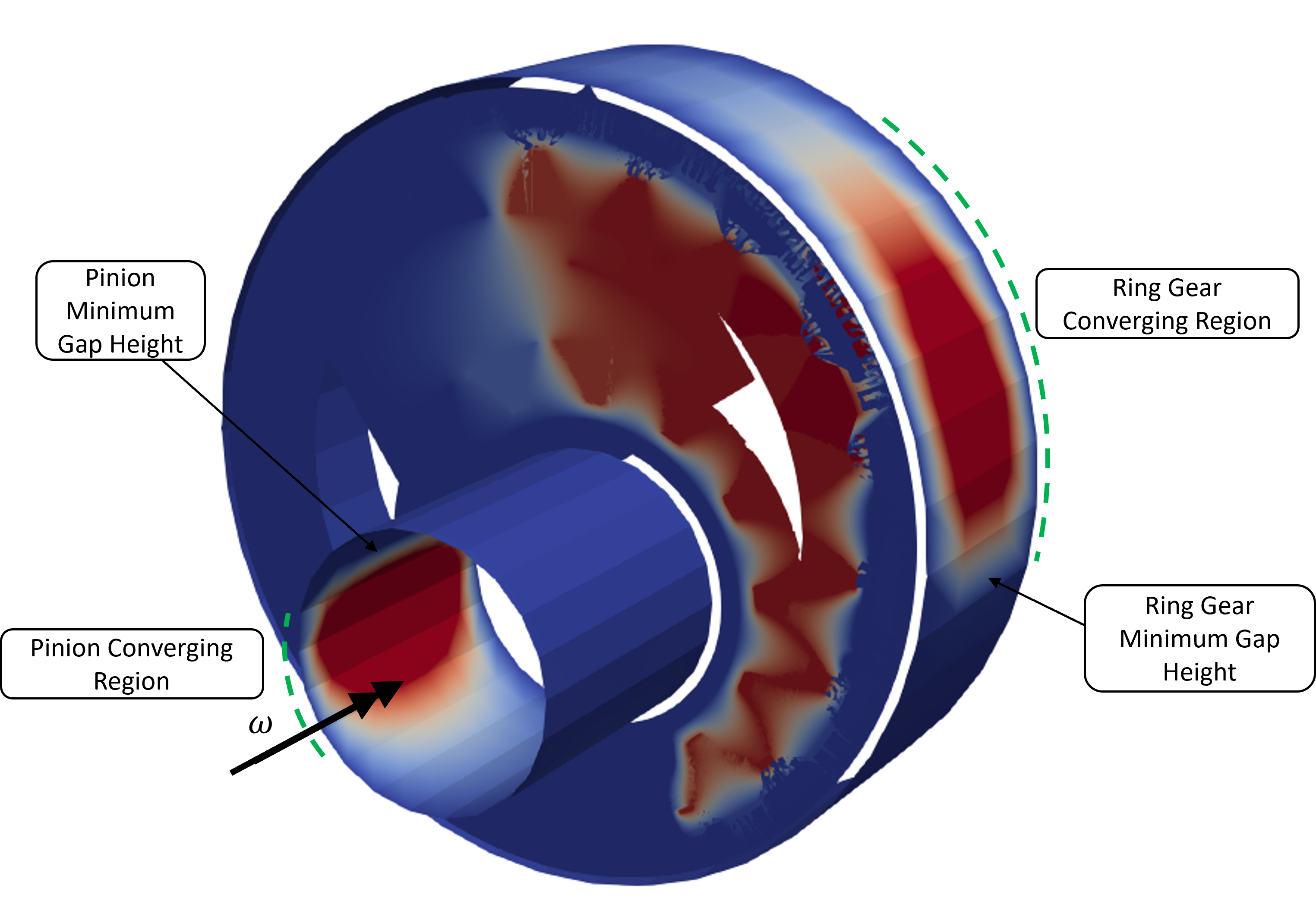
The results obtained in the journal bearings aligns with the simulation set up. The high pressure generated in the internal volume of the gear set pushes the ring gear rightward, where consequently is located the minimum gap height. Knowing the rotation direction of the gear set it is possible to identify a converging and a diverging region of the journal bearing gap. In the converging region is built the high pressure that supports the ring gear. On the other hand, the high pressure generated in the IGM pushes the pinion leftward. This locates the minimum gap height in the left side of the pinion journal bearing and, as before, it is possible to identify a converging and a diverging region. In the converging region is built the pressure that supports the pinion load.
The pressure distribution is not the only result that can be plot. Other interesting results can be observed plotting the gap height.
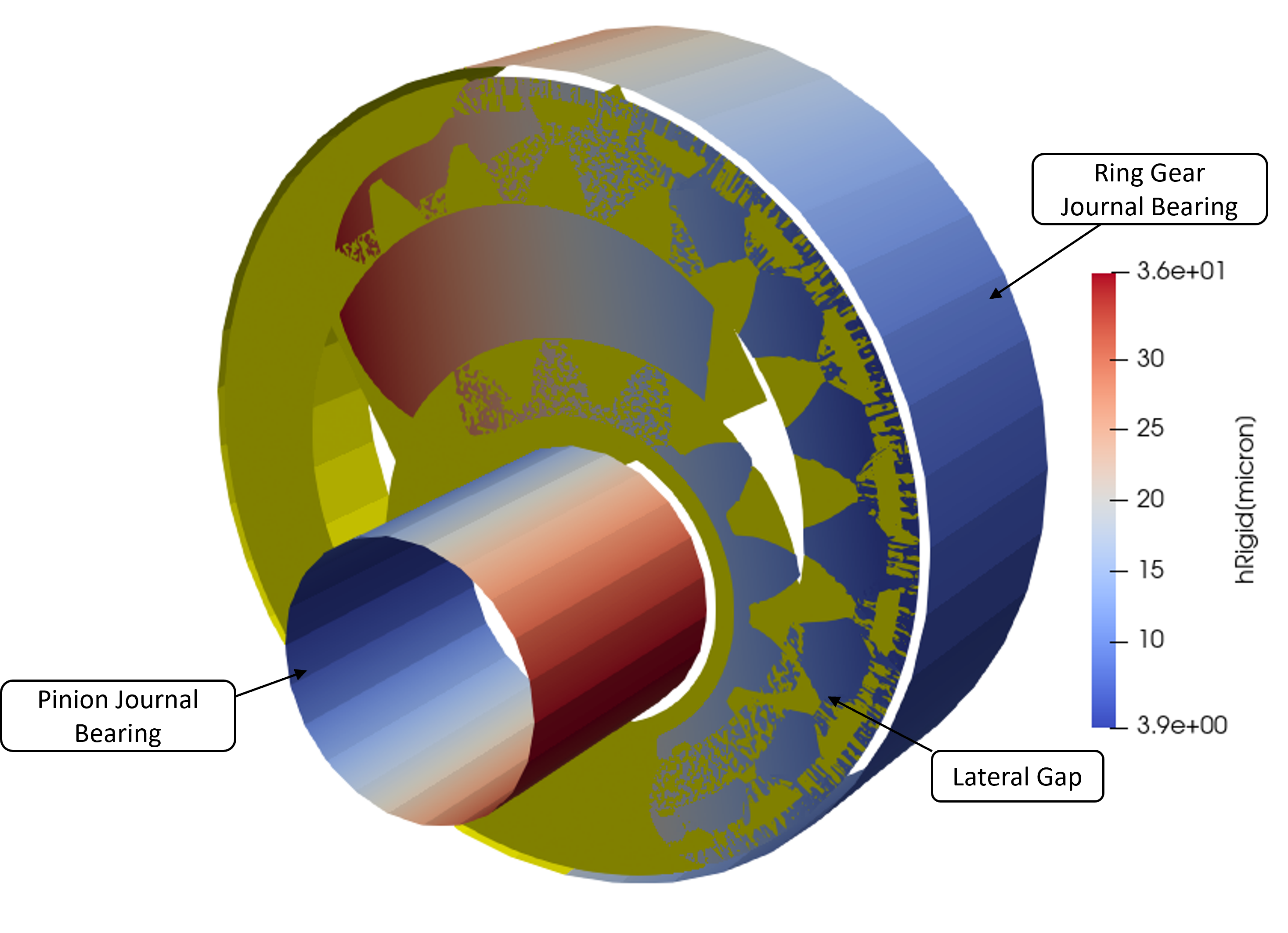
In the image it is possible to see that the plate is not parallel with respect to the gear set lateral surface. More precisely, the gap is smaller closer the high pressure region. This behavior is desired because it mitigates the leakages, and can be obtained with the proper design of the axial compensation system. Looking to the journal bearing instead it is possible to see that the minimum gap height location is where stated in the earlier paragraph.